
ZX81/TIMEX-SINCLAIR 1000 3D Printed Case - Part 2

This is the second post in a series on designing & prototyping a ZX81/TS-1000 enlarged case, code named "Kilo-Zed". It covers the changes & improvements from version 1.0 to version 2.0. If you haven't already read Part 1 of this series, you may do so here: ZX81/TIMEX-SINCLAIR 1000 3D Printed Case - Part 1. Towards the end of the post I share a keyboard troubleshooting experience, brought on by a mistake I made while modifying the motherboard's keyboard headers.
Improvements On Version 1.0
My brother and I were extremely excited with the progress and results we were seeing on the first prototype of the Kilo-Zed 3D printed case, but there were some changes that would need to be made. After playing around with the last version of the case, and doing some trial fit-up of the mechanical keyboard and the motherboard, it was clear that we would need to go back to the drawing board. I must confess that I feel funny calling the ZX81 circuit board a motherboard, it's so tiny that it should be called a baby-board. 🤣
Improvement 1: Sink The Keyboard
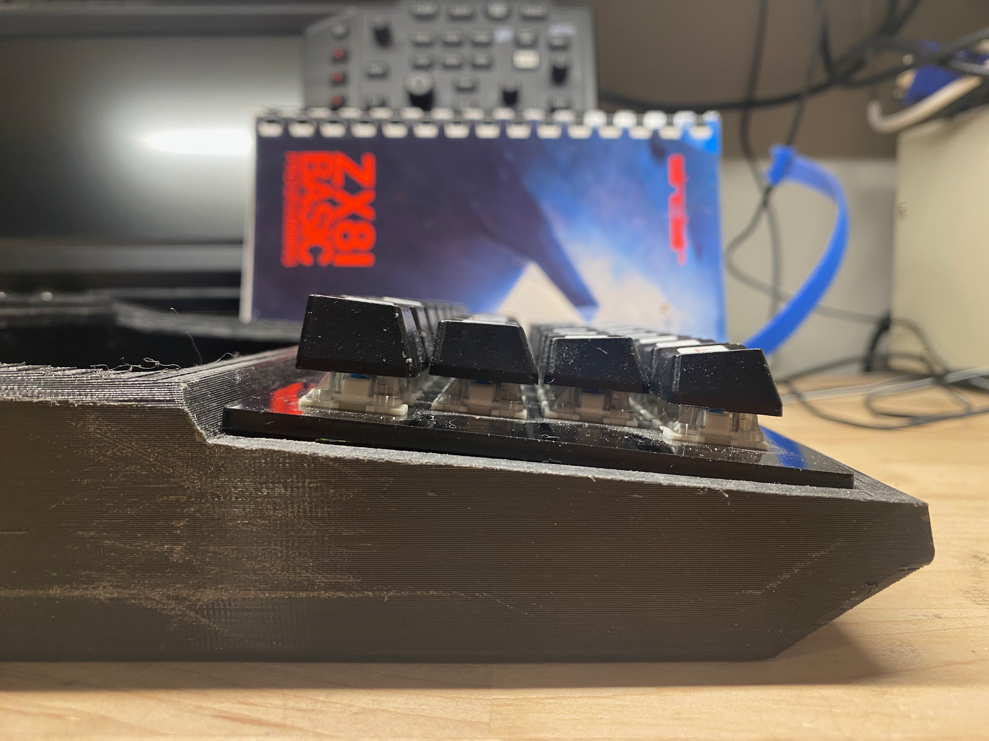
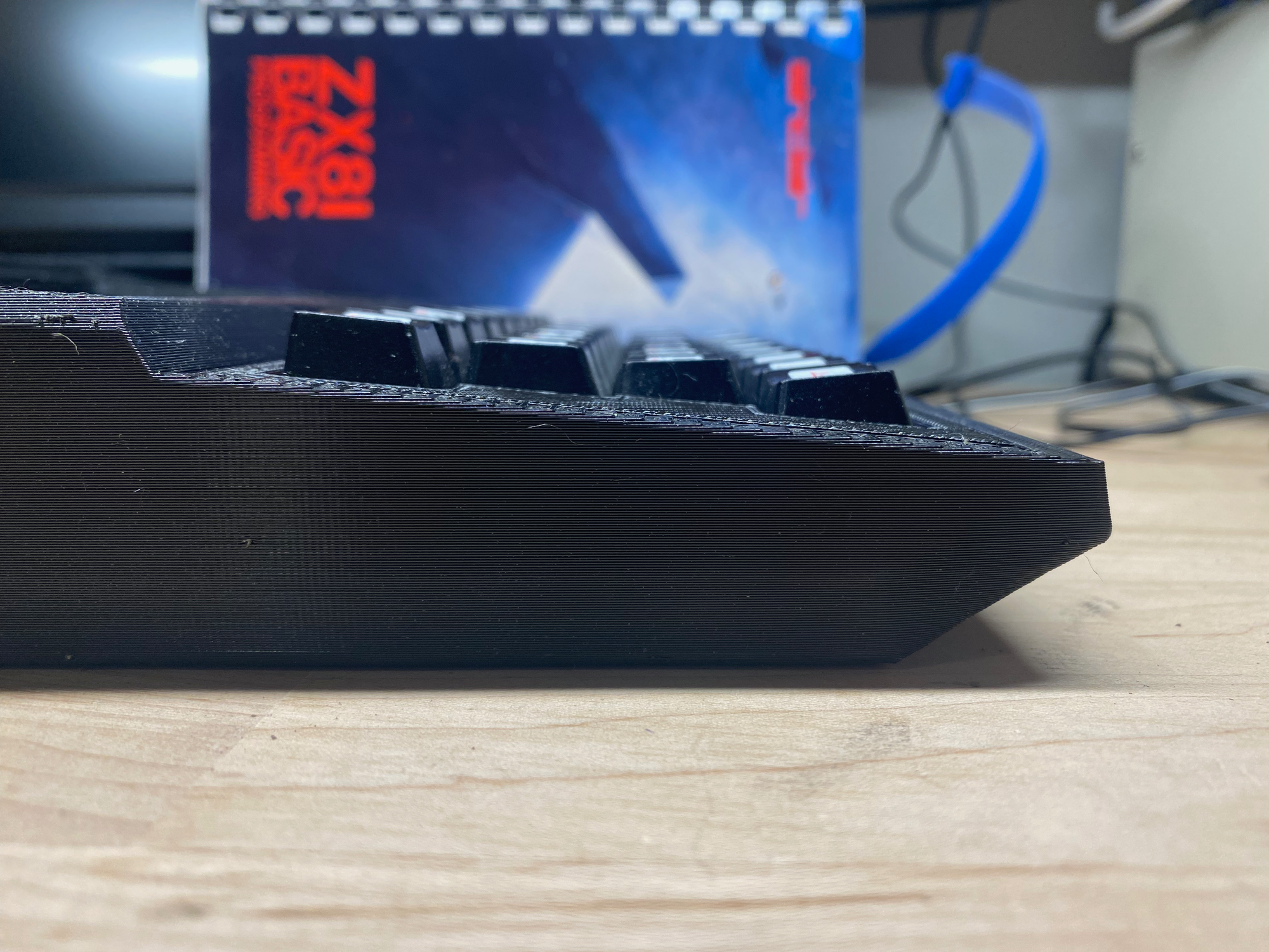
The first thing that needed to be improved upon was how far the mechanical keyboard was sticking out from the case. Aesthetically, I didn't like it at all. The keyboard was sitting way too high, taking away from the "brow" (the surface that rises up from behind the keyboard to meet the top of the case).
Functionally & ergonomically, the position of my hands were not as comfortable as I would have liked while typing. The solution would be for my brother to go back to his Pro/ENGINEER application to modify the model and sink the keyboard plate support into the case an additional 12mm for a total of 13mm.
Lowering the keyboard was significant and really made everything look much better, but now with the keyboard sunk into the case, it created a definite gap/void surrounding the key caps. To remove the gap surrounding the keyboard, I went into FreeCAD and designed a spacer plate just for this current prototype version. I wanted to be able to get a visual and tactile sense of the look and feel of the next version of the case following this iteration.
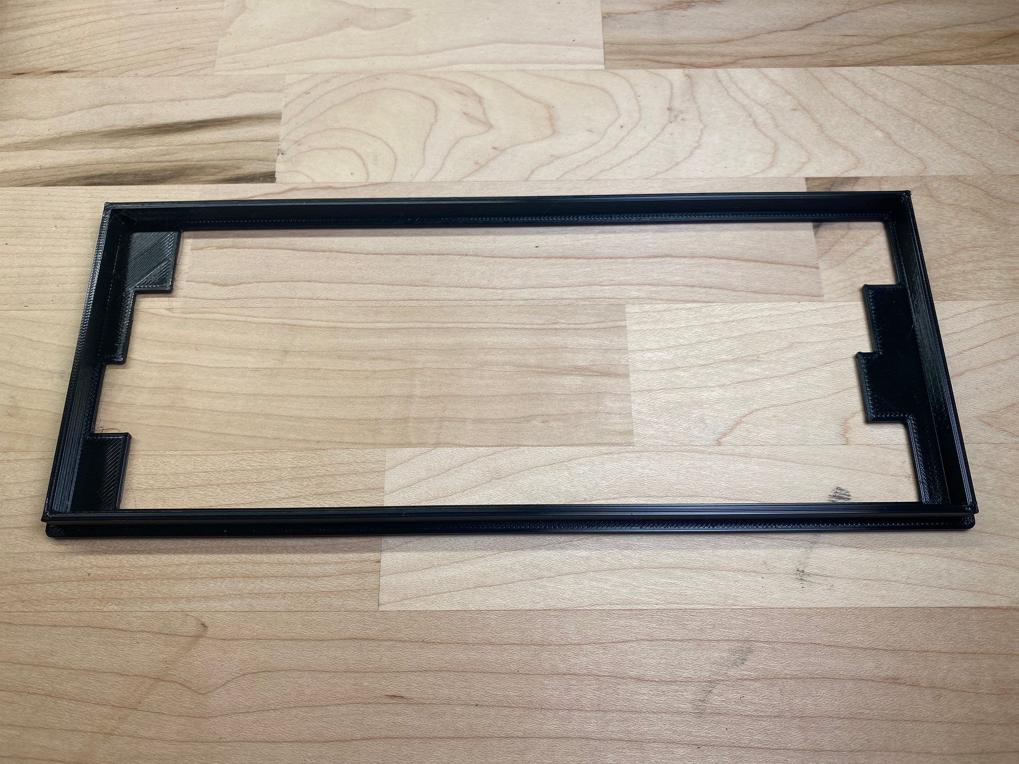
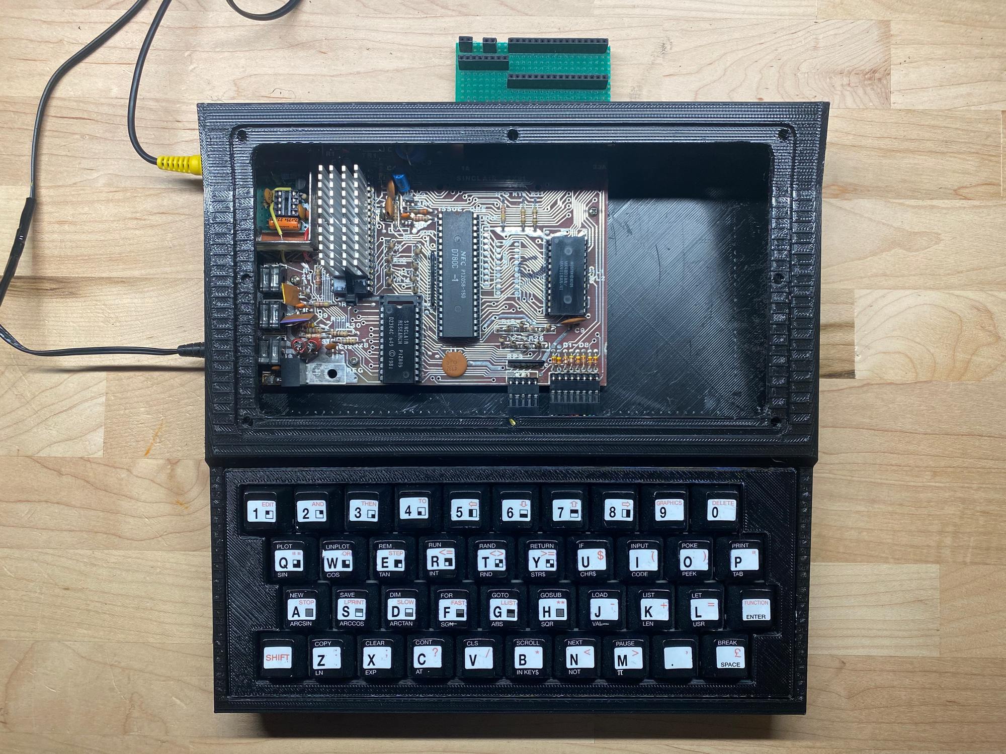
The results of the spacer plate can be seen on the feature image at the beginning of this post. The next version of this case will require some serious redesign on how the keyboard will be connected to the case, and that will certainly integrate this spacer into an upper half of the new case.
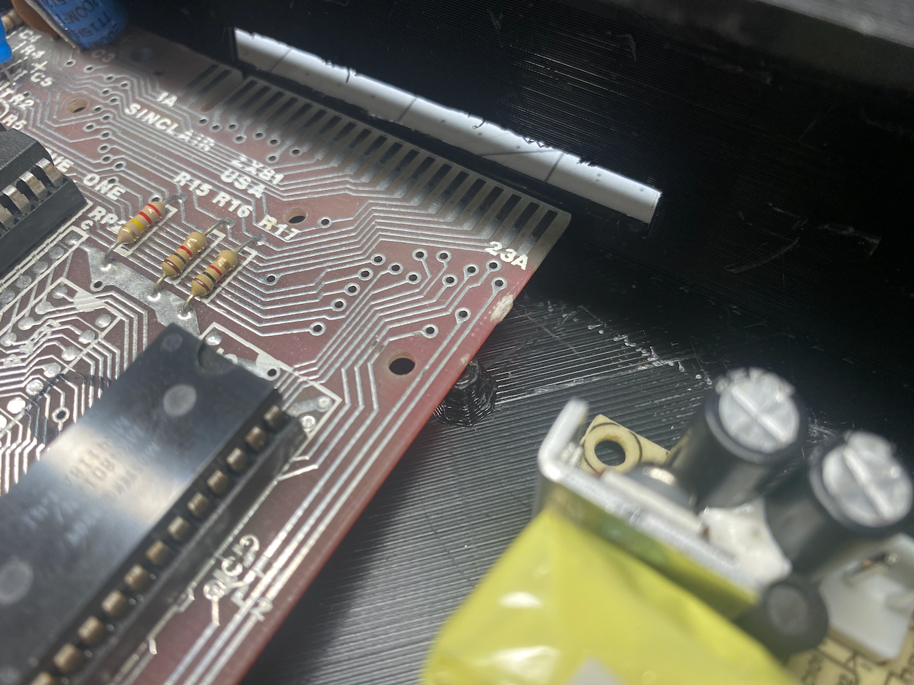
Improvement 2: Circuit Board Stand-Offs
In Version 1.0, and as mentioned at the end of the first post in this series, the circuit board stand-offs were small and flimsy, and I broke one off while removing the supports from the 3D print. Additionally, after seeing the Version 1.0 stand-offs physically for the first time, it was clear that if I tried to use one of the 2mm x 6mm self tapping screws in them, they would likely break due to the lack of material around the hole.
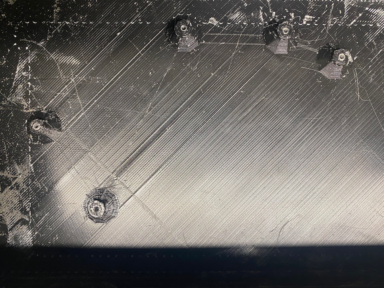
In addition to asking my brother to enlarge the stand-offs to 7mm in diameter, I also asked him to replace one of the stand-offs with one in a different position, right behind the "Ear" jack.
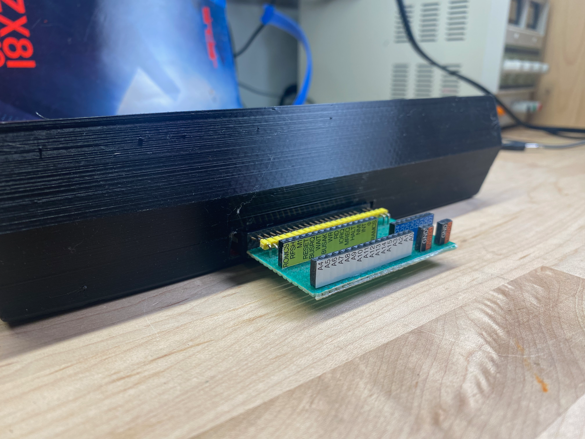
Improvement 3: Enlarge the Expansion Port Opening
The opening in the back of the case exposes the expansion port of the computer, an edge card connection that can be used for a memory expansion module, a printer, and an external keyboard. In the version 1.0 case, the slot was simply too narrow to accommodate an edge card connector, so version 2.0 included changes in those dimensions.
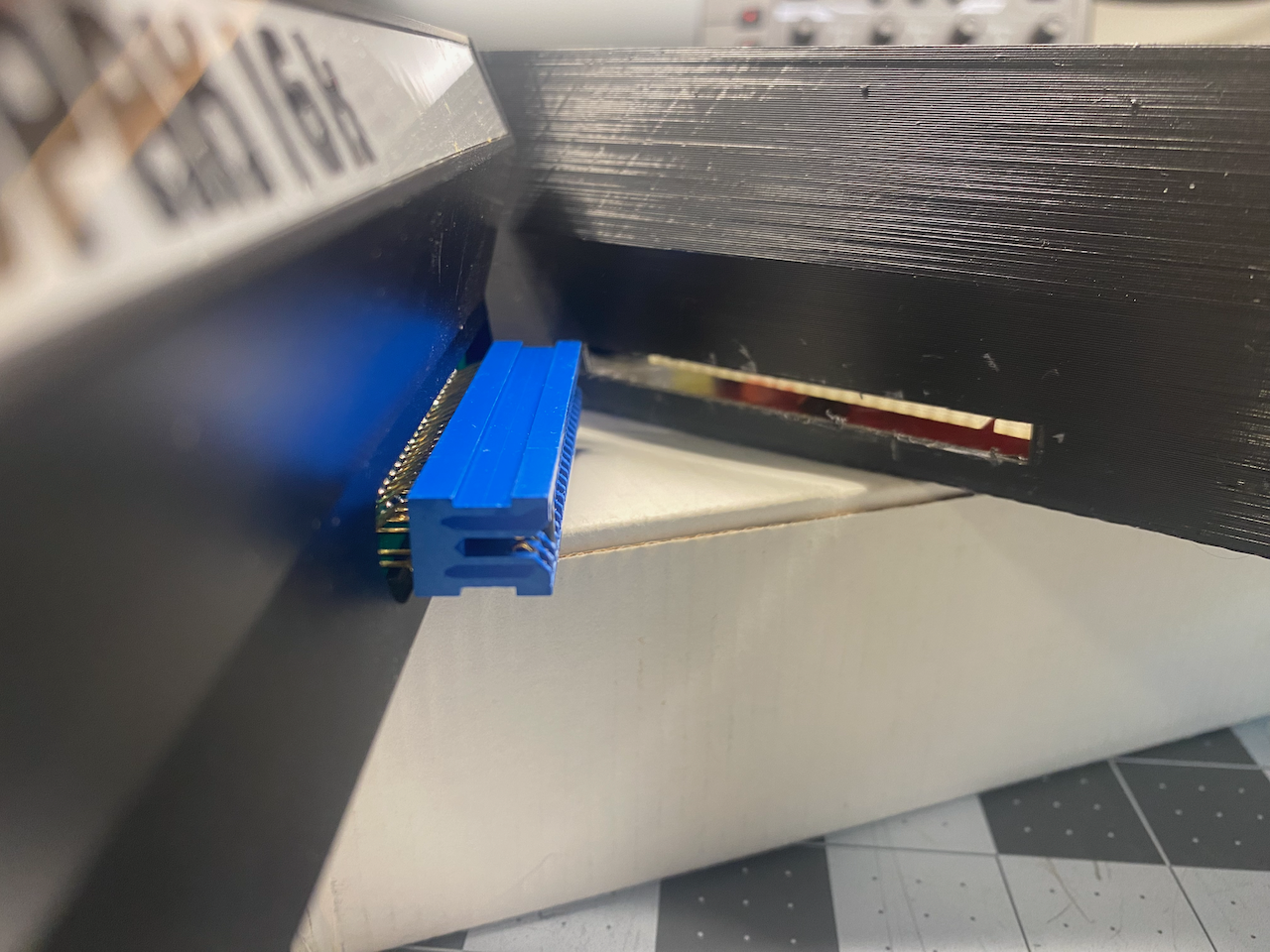
The expansion port opening on version 2.0 of the case was much closer to the correct size, but still needed 1mm to be taken off of the top and bottom. A short time with a small file did the trick. I was able to plug in my DIY ZX81/TS100 Breakout Board for prototyping new peripherals!
Motherboard Header Modification
One last thing that I felt needed changing was the two vertical pin headers that I had originally soldered onto my brother's motherboard when I replaced the original keyboard ribbon headers (I did the same to my TS-1000). The pin headers were added to connect the new mechanical keyboard via Dupont connectors, but in this prototype case the fit was less than ideal, so I changed the headers from straight/vertical headers to right angle/90 degree headers.
Something interesting happened after I finished soldering the new right angle headers and went to test the keyboard... I noticed that I couldn't get the PRINT command to appear (above the P key). I was trying to do the obligatory "HELLO WORLD" program, but no dice! I tried the O key, I, U, and Y, but none of the keys worked. I knew that they share the same row on the keyboard matrix, which is also the same Address line, A13.
When I checked continuity with my meter everything looked fine from the switches all the way to D5, the diode that connects that row of the keyboard matrix to A13 of the Address Bus, so what gives?
Keyboard Troubleshooting
I felt the only explanation for all the keys in the A13 row not working while also having continuity all the way through to A13, was that this row of the keyboard has continuity to a neighboring row & Address Bus line. Understanding how the computer decodes key strokes was the key (pun intended) to knowing what the problem must be before actually finding the problem.
I used a trick I learned from this YouTube video to de-solder the vertical keyboard headers. It involves smothering all the pins in solder at the same time, thereby heating all the pins at once, and allowing the header to be removed in one piece. Using that trick for the first time, I may have missed some excess solder, or I used too much solder when putting in the new headers, bridging the gap between two header pins. With my multimeter I was able to measure that the D5 (A13) header pin had continuity to D6 (A8). I further confirmed the issue when trying to get the computer to recognize key presses on the SHIFT, Z, X, C, and V keys, which were also not registering.
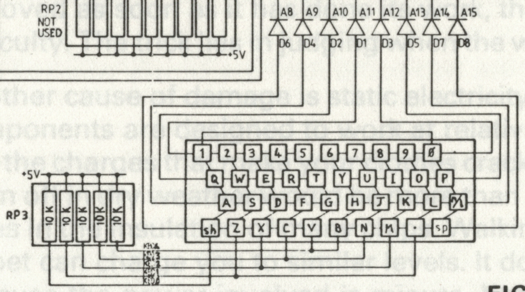
I need to mention that the schematic above shows D5 and D6 far apart from each other, when on the motherboard they are neighbors. In fact, the diodes are in numerical order from left to right, viewed from the component side of the circuit board.
Finally, desoldering the right angle header for the Address Bus pins, cleaning all the flux with isopropyl alcohol, and soldering a new header did the trick, and all was well with the keyboard, the computer, and the universe.
I am not going to go into detail of how the ZX81 decodes the keyboard in this post, but if enough subscribers request it in the comments, I will attempt to explain it in another post dedicated to the ZX81/TS-1000 keyboard. In fact, if I'm not mistaken, the other Timex-Sinclair computers work in the same way. There is a lot going on, and it is a testament to the brilliant engineering by Clive Sinclair's team.
Things Still Requiring Adjustments
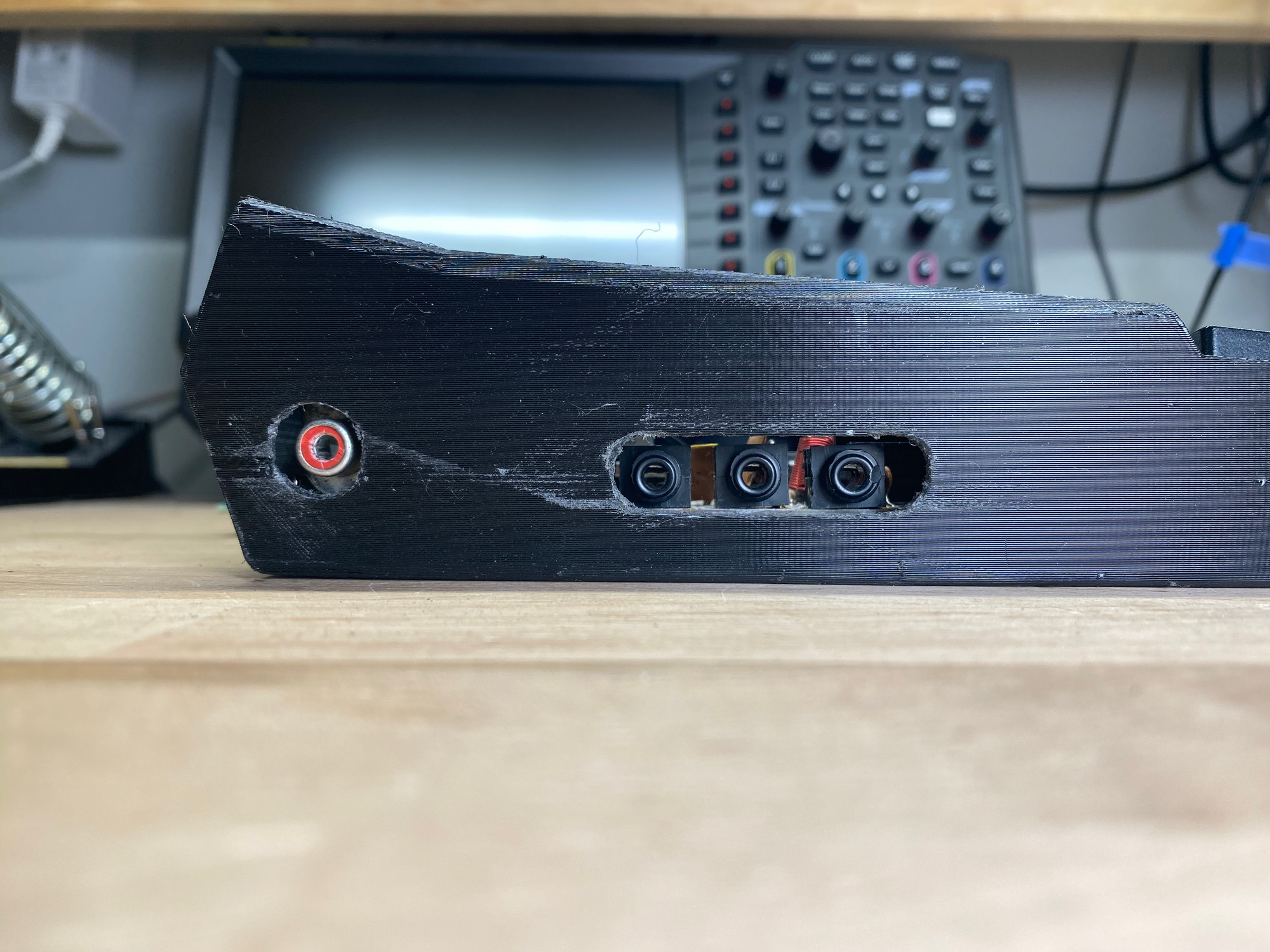
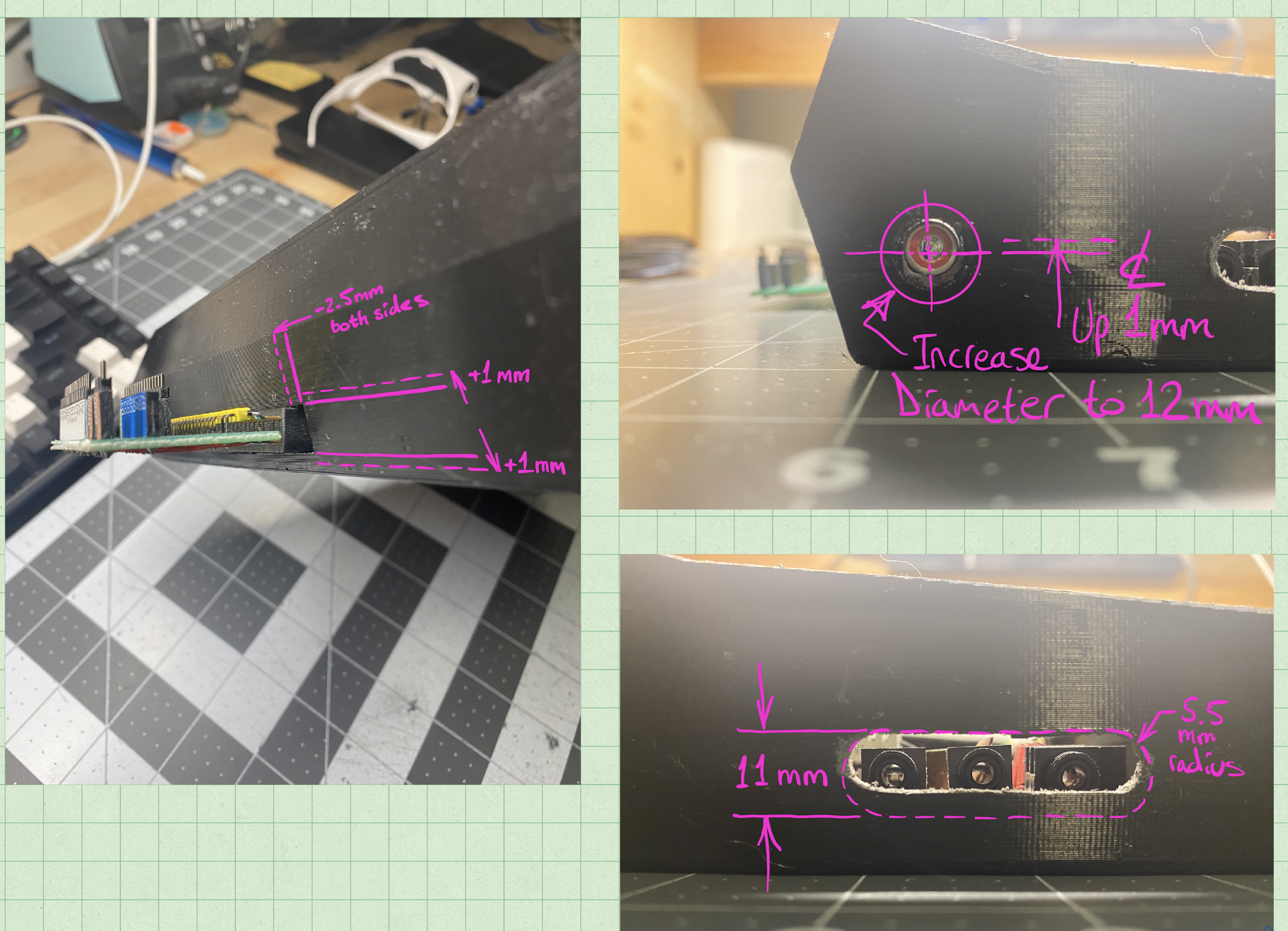
My brother has been working from a bare motherboard of a junked ZX81 that someone attempted to assemble without success (the motherboard for his Zeddy is the one you see in these photos, as it is still in my possession for the remaining modifications and blogging). Since the motherboard my brother has is bare, he can only guess at some of the opening dimensions, and for that reason, I had to file open the hole for the composite video jack (it used to be the RF modulator, but was modified in this post), and for the 9VDC power, "Ear", & "Mic" ports.
I took photos and marked them up on my iPad Pro using one of my favorite apps, Notability, to indicate the changes and the new dimensions for my brother to update the model in Pro/ENGINEER for the upcoming version 3.0.
It's really cool to work in CAD applications, virtually modeling something in software, and then rapidly generating a physical prototype on a 3D printer. I wish my brother and I had jumped on this technology sooner, so much fun! Stay tuned for version 3.0 of the Kilo-Zed case.