
ZX81/TIMEX-SINCLAIR 1000 Composite Video Mod Part 2 - Plus Troubleshooting


Part 1 of this two part series documents one possible way to perform a DIY composite video mod on a ZX81/TS1000 with the newer ULA 2C210E, as opposed to the older ULA 2C184E. The main difference between the two versions of the ULAs as far as video output goes is that the older ULA does not generate a "back porch".
This post has a little "off topic bonus" of troubleshooting the ZX81 in connection with the composite video mod that I was attempting for my brother's ZX81.
If you haven't read Part 1 yet, parts of it could be of interest even if you are reading this just for the information pertaining to the older ULA.
Spoiler Alert!
This post was supposed to chronicle one way to perform a DIY composite video modification on a ZX81/TS1000 with the older ULA 2C184E, but *%@! happens, and that changed things in an interesting way. I still cover the DIY composite video mod for the older ULA minus the full test. This post has a bit of a twist, a lesson learned for me to share, and should not disappoint.
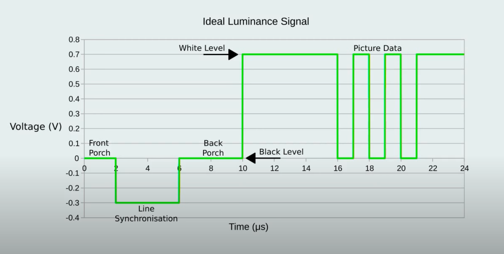
What is a Back Porch, and why do I need one?
The back porch occurs immediately after the horizontal line synchronization pulse, and lets the display know what voltage level should be used to display black. The back porch lasts about 4 microseconds and is followed by the picture data. In the case of the ZX81 and TS-1000, there is only black and white, so now that the display knows what voltage level is black, the other voltage level will have to be white, or full luminance.
My Brother’s ZX81
My brother shipped his ZX81 to me so that I could perform the composite mod on it and blog about it. If you haven't read Part 1 of this two part series, I purchased a Sinclair ZX81, a TS1000, and associated gear on Ebay in unknown state of functionality solely for the purpose of tinkering🤓. The thing that is interesting is that I kept the TS1000 which had a new version ULA, and my brother's ZX81 had the older version ULA.
JoulesperCoulomb's Composite Video Mod
When I realized that I was not going to do the composite video mod on my brother's ZX81 the same way as on my TS1000, I did a search on Duck-Duck-Go and found a great source of information from JoulesperCoulomb. On the linked miscellaneous projects page there is a link to a very informative YouTube video, and an Adobe PDF document with instructions on how to build a composite video mod on stripboard.
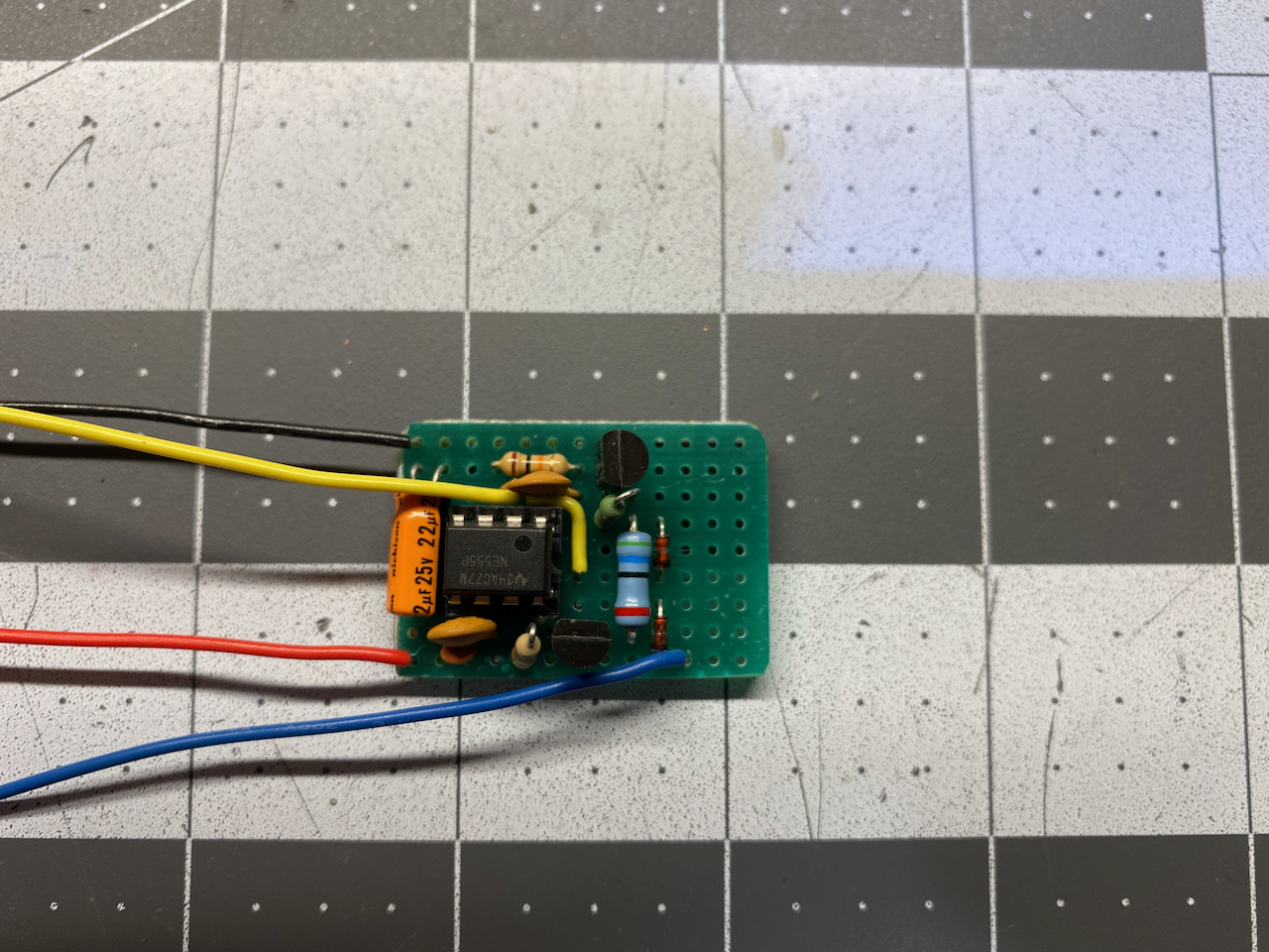
The build document provided by JoulesperCoulomb gives two different circuits to build: one with all discrete transistors, and one using the infamous 555 timer integrated circuit. I opted for the 555 timer build version.
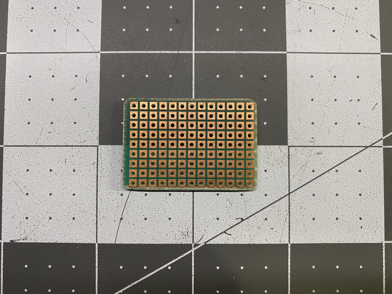
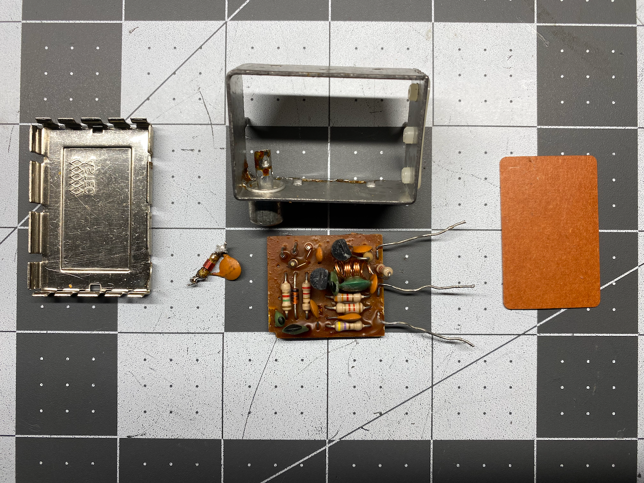
I didn't have any stripboard on hand, but I did have perfboard coming out of my ears, so I cut a piece of perfboard small enough to fit inside of the RF modulator housing.
Since I was using perfboard instead of stripboard I would have the option of changing the layout of the components from the nice layout provided by JoulesperCoulomb (My father always said, "Why make it easy when it can be made difficult"). Granted a bit more work and effort, but it was fun for me. Once I had gone through several dry fits of the various components on the stripboard, I soldered them in.
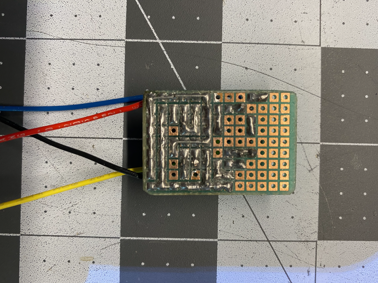
I ended up making actual +5VDC and ground rails on the bottom of the board as shown in the photo above. Not shown in the photo: I later trimmed the last two columns of the perfboard when it was clear that everything fit, but didn't take a photo of it until it was mounted in the RF modulator case. Now it was time to check my brother’s ZX81 to see if it was outputting a video signal from pin 16 of the ULA...
Ruh Roh...No Video Signal From Pin 16!!!
In the Introduction, I mentioned a lesson learned: It would have been wise to check my brother's ZX81 first before doing the entire build for the old ULA, but that would just make too much sense. I can hear the voice of my father in the back of my mind (LOL).
Troubleshooting the ZX81
I am no expert in troubleshooting computer electronics, but I am learning. Thanks to many years of troubleshooting industrial equipment, I have developed a few proven methods for systematically checking the parts of a system in a logical sequence to find what is wrong. The ZX81 is not much different from other things that I have diagnosed, and besides that, I have learned a lot building a Z80 based computer from scratch that should help to figure it out.
Check the Power Supply
Whenever troubleshooting anything electrical, which includes electronics, one should check the power supply before looking anywhere else. The ZX81 and the TS1000 both get power from what is labeled as a 9VDC power supply (it is typically more like 11VDC or thereabouts) via the two pole 3.5mm power jack on the side of the computer.
The 9 Volt supply is fed to a 7805 linear voltage regulator which almost literally burns off the excess to output a regulated +5VDC for the ZX81's circuitry (hence the reason for the aluminum plate mounted to the 7805). Many ZX81 owners have modded their "Zeddies" to use modern switch mode regulators which are more efficient than the 7805, also allowing them to ditch the heat sink.
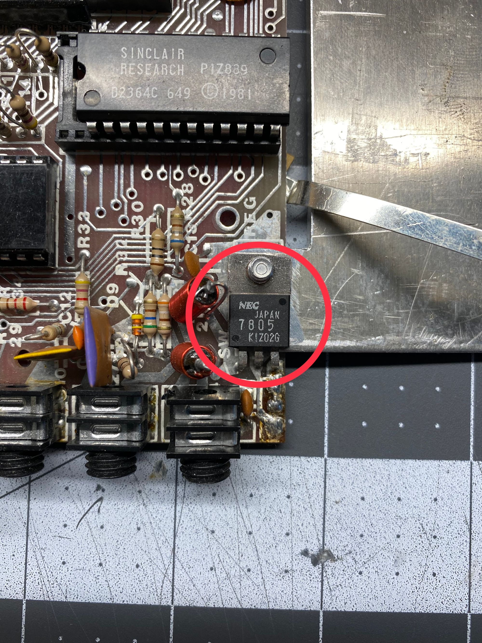
Checking the power supply at all of the following locations:
- +5VDC being output from the 7805 with reference to ground (+5VDC on the pin at the outer edge of the board, ground on the middle pin)
- The Z80 microprocessor (+5VDC on pin 11, ground on pin 29)
- The ULA (+5VDC on pin 40, ground on pin 34)
- The ROM (+5VDC on pin 24, ground on pin 12)
- The single chip RAM IC4 (+5VDC on pin 24, ground on pin 12) or the two chip RAMs IC4a & IC4b (+5VDC on pin 18, ground on pin 9)
Everything regarding power supply checked out as far as I could see, so the next thing I chose to check was the system clock...
Checking the System Clock
One very quick and simple way to check if a computer is doing anything at all, or "given up the ghost", is to put an oscilloscope on the microprocessor's clock input pin. In the case of the Z80, the clock input is on pin 6, and when I put my oscilloscope on pin 6 I saw NOTHING!
The ULA Does More Than Output Video
The ZX81 has a clock oscillator made from a 6.5 MHz ceramic filter identified as X1 in the schematic below. The output of the 6.5 MHz clock circuit is fed directly to the ULA (IC1 - SINCLAIR COMPUTER LOGIC) on pin 35. The ULA, which is responsible for video output, uses the 6.5 MHz signal to synchronize the video output and it also divides the signal's frequency in half to output a 3.25 MHz clock signal to the Z80 microprocessor, IC3.
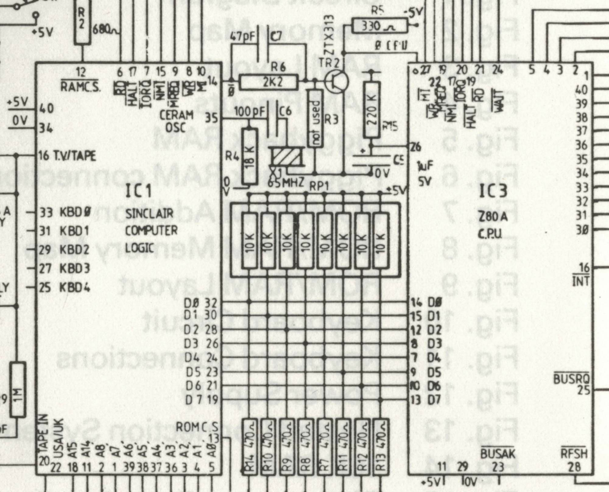
The 3.25 MHz signal is output from pin 14 of the ULA and then is amplified by transistor TR2 to supply the Z80 with a clock. When I checked the output of pin 14 from the ULA, there was nothing. I was more disappointed than surprised as I have read in more than one place that the old ULAs are notorious for getting too hot and failing. At this point I stopped troubleshooting, fairly convinced that the root issue on my brother's Zeddy was a bad ULA.
I began searching online for a replacement old version ULA, but came up empty handed. What I did see was not guaranteed to be in working order, so I decided that in order to get my brother's Zeddy working I would need to fit it with a newer ULA or a modern replacement such as the VLA81. I decided on finding a new old stock, and tested/verified ULA 2C210E. I knew that Zebra Systems in Brooklyn, NY would either have ULAs or would know if anyone else still had any. I was in luck, Zebra Systems had some, so I purchased two ULA 2C210E ICs from them.
New ULAs Arrive From Zebra Systems
Once the new ULAs arrived, I eagerly installed one in my brothers Zeddy, applied power, and checked pin 6 of the Z80 CPU. At least that appeared to fix the "no clock" problem, now there is a steady 3.25 MHz clock signal to the CPU. Next, I checked the video output on pin 16 of the ULA for the video output signal, and that was there as well!
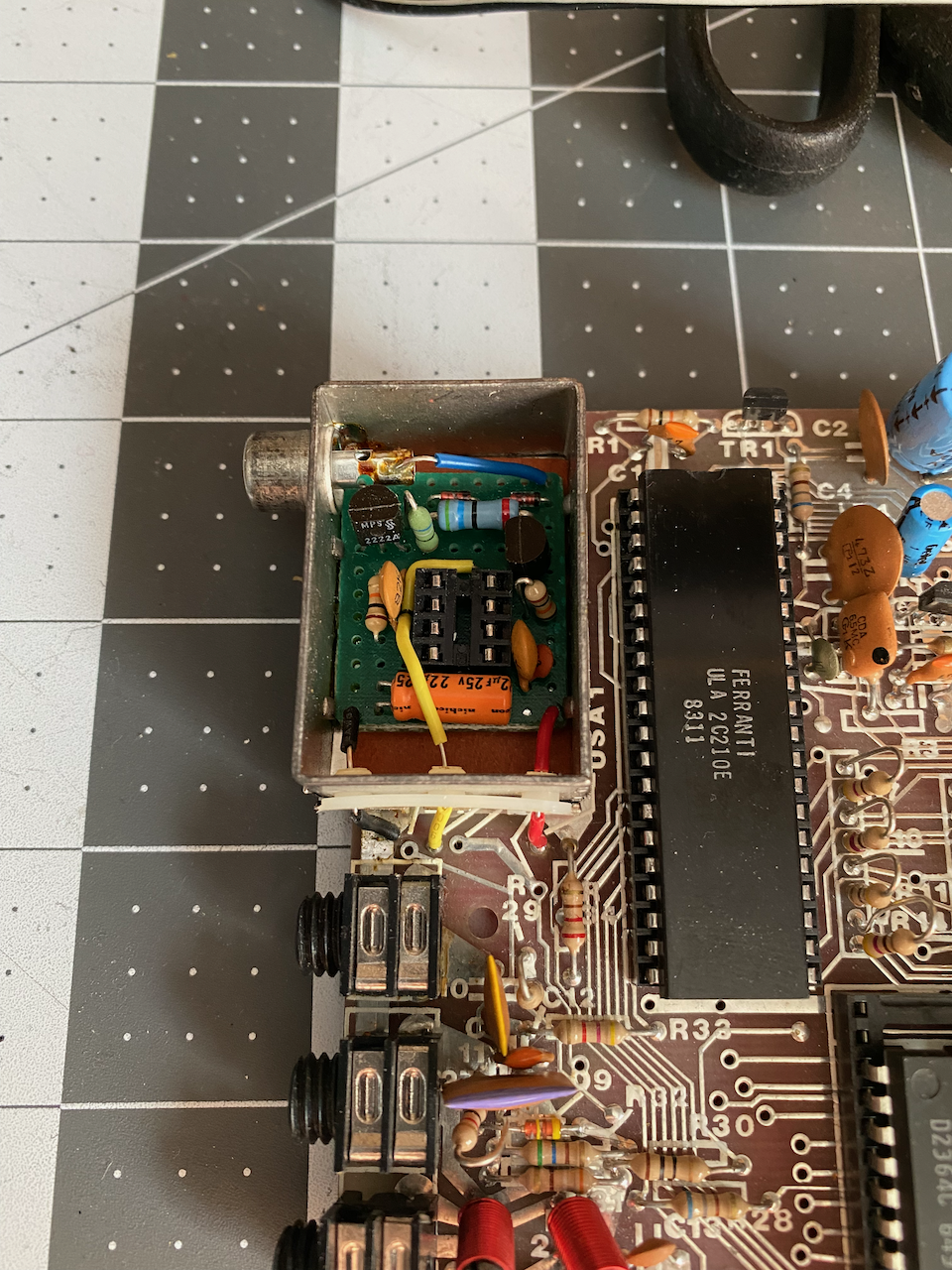
I removed the 555 timer IC from the IC socket since the new ULA generates it's own back porch. The only parts of the mod in use now are C1, Q1, R4, D1 & D2. With everything on the ZX81 working as far as I could tell at this stage, I used jumper wires to temporarily connect the composite mod board to the ZX81 and was greeted with an inverse K at the bottom left of my LCD monitor!
I desoldered the channel switch and soldered in a jumper to permanently send +5VDC to the USA1 connection near the RF modulator. I had already desoldered the RF modulator and removed the original circuit board from the housing, so now I could mount the new board inside the RF modulator housing and solder everything to the ZX81 pcb.
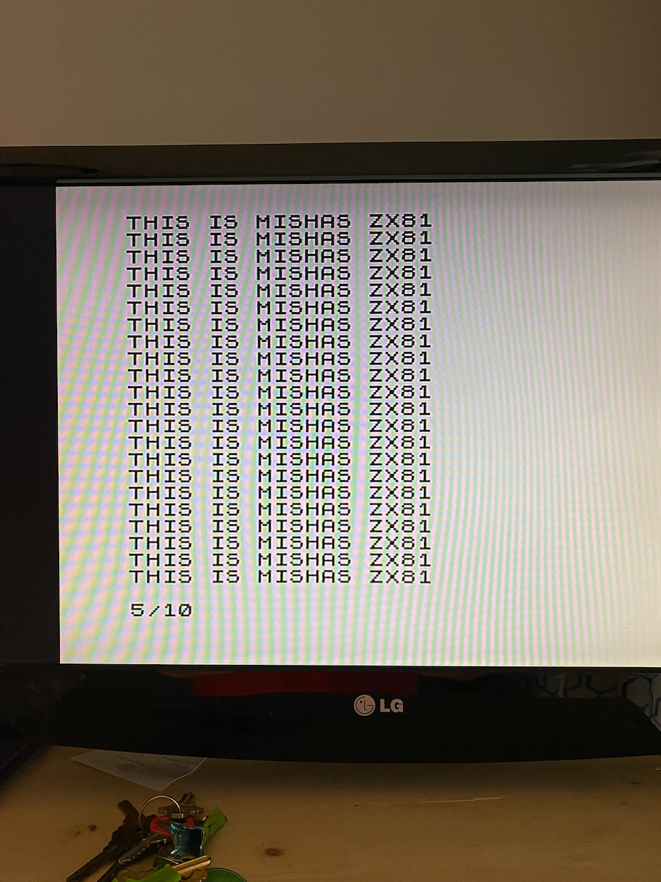
The only thing left to do was the obligatory two line PRINT -> GOTO loop in BASIC and then text a photo of the screen to my brother.
Challenges like this have their moments of discouragement, but the learning experiences are well worth it. Stay tuned for the next ZX81 post on making a custom mechanical keyboard!
Sources
YouTube Video: ZX81 Video Conditioning by JoulesperCoulomb
PDF Document: ZX81 Video Conditioning by JoulesperCoulomb