
ZX81/TIMEX-SINCLAIR 1000 - DIY Breakout Board

This post covers how I made my own breakout board for prototyping new circuits for my TS-1000. The end result plugs into the expansion port/card edge of a ZX81/TS-1000, has female headers for jumper wires that can be connected to a breadboard, and allows for prototyping and testing new circuits while temporarily connected to the computer.
Prototyping Cards/Boards
Prototyping cards/boards are printed circuit boards which are designed for adding Dual Inline Pin (DIP) ICs (Integrated Circuits) and other through hole components in an organized & flexible way.
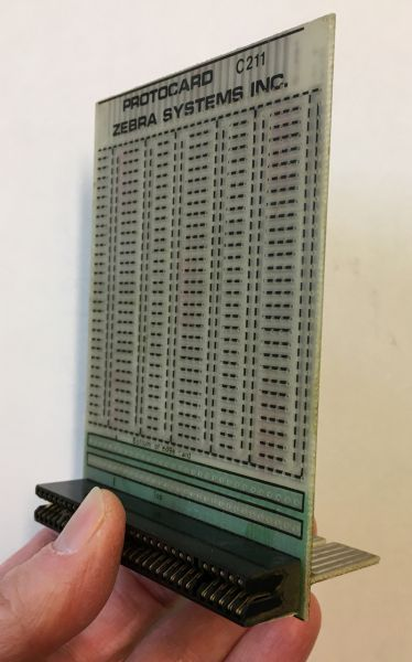
My friends at Zebra Systems sell Protocards & connectors for the ZX81/TS-1000 & TS-2068, and a lot of other rare, hard to find Timex - Sinclair goodies. Like most of your better prototyping boards, the ones that Zebra Systems offers also provide VCC and Ground power supply rails alongside all of the columns where you would place your components. Everything can be easily soldered on to the Protocard to make circuits with small jumper wires between different points, thus making the prototype circuits without needing to design and manufacture a Printed Circuit Board (PCB).
Even with various global PCB manufacturers delivering low cost PCBs with relatively short turn around times, the development time and cost would most likely increase compared to using prototyping cards/boards.
Solderable prototyping cards/boards are great when you already have something mostly figured out, and almost ready for a custom PCB, but that may still require component changes or fine tuning.
The one thing about prototyping cards/boards is that if you want to make a change you will need to get out the soldering iron.
I wanted to have a less permanent way to experiment/prototype circuits connected to my TS-1000. I like breadboards for prototyping and tinkering, so I wanted a way to connect a circuit built up on a breadboard to the edge card connection on the back of the computer.
Breakout Boards
Breakout boards allow one to get access to a number of significant points in a system, and in the case of the ZX81/TS-1000, a breakout board allows easy access to all of the signals brought out on the edge card connection that was added by Sir Clive Sinclair and his merry crew of digital electronics engineers! 🤓🤓🤓
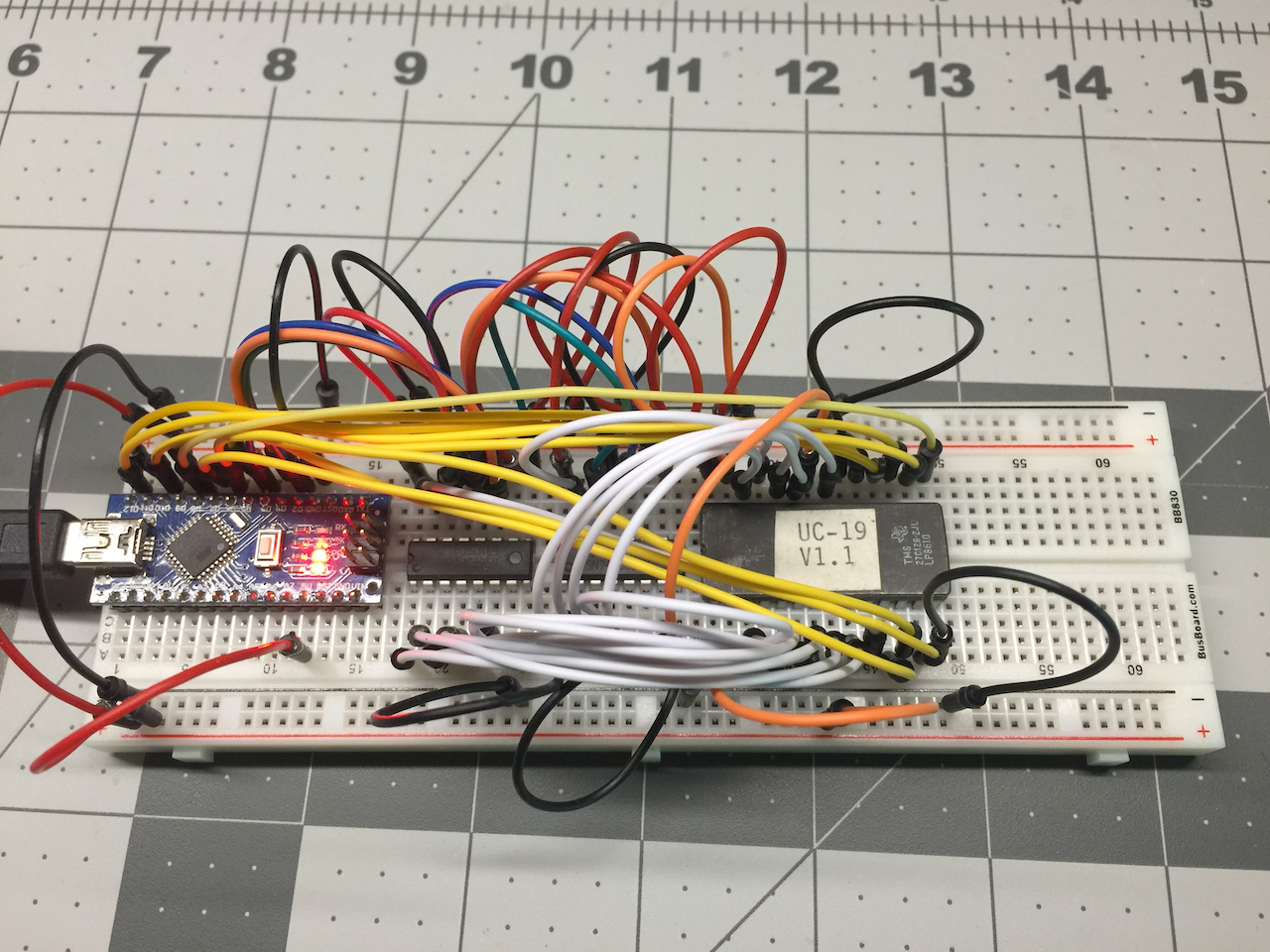
I had already built a breakout board for my DIY 8 bit computer project, a board that provides easy access to the signals on the Eurocard backplane, so why not do the same thing for my Zeddy?
The breakout board for the DIY 8 bit computer brings out all of the control signals, address bus bits, and data bus bits of the Z80 microprocessor onto simple headers that I can run jumpers wires to/from.
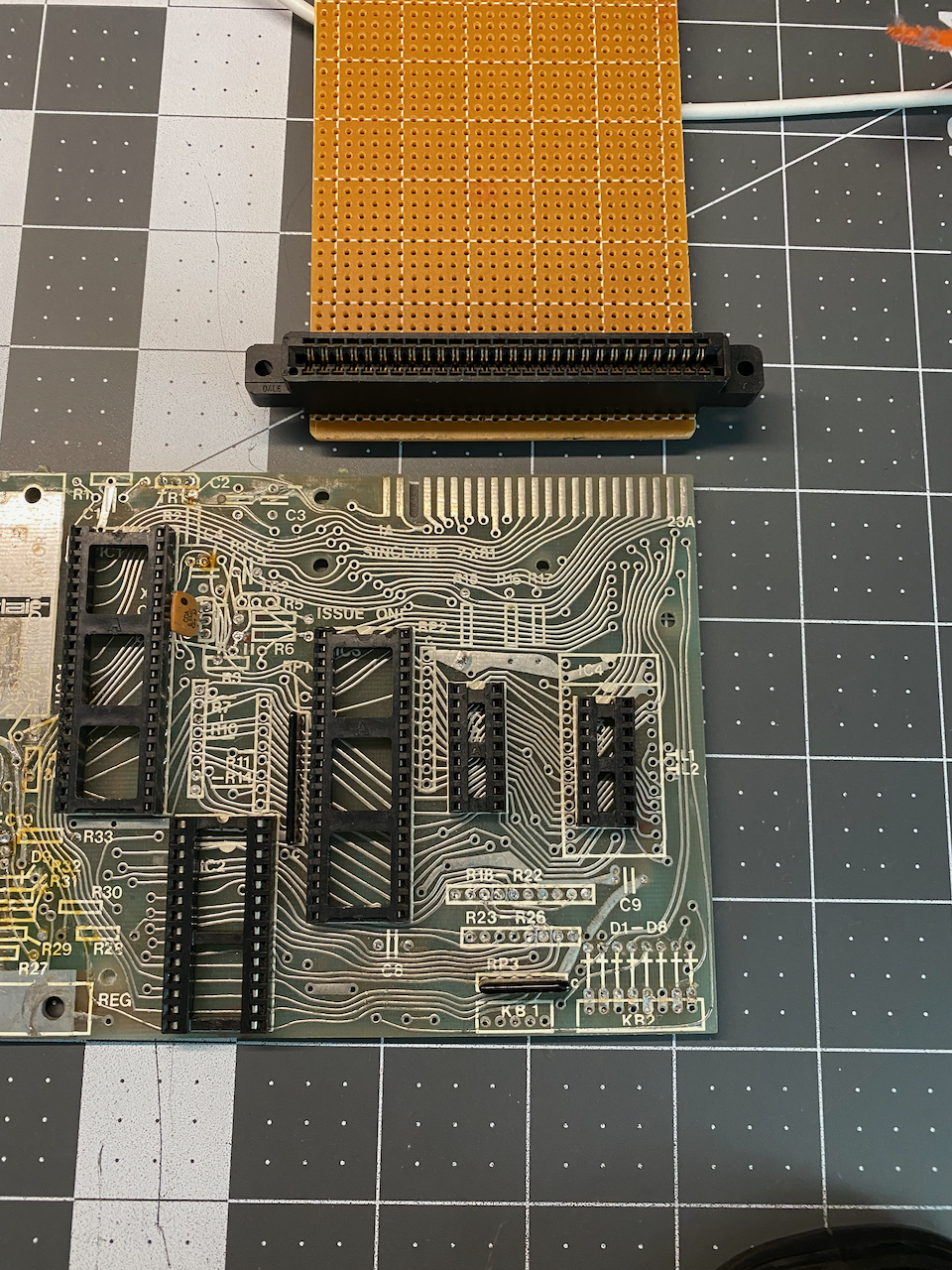
Standard Edge Card Connectors
When looking around online for a source for edge card connectors, I was unable to find anything that would work on the back of my TS-1000. All of the edge card connectors I could find were closed on the ends, and I needed something that was open on both ends.
Since what I needed didn't seem to be available online (I later checked with Zebra Systems, and they have connectors), I decided to check my local "Brick & Mortar" electronics store which happened to have a bunch of edge card connectors that they just wanted to get rid of, so I got a great deal on them! I am really glad that there are still some brick & mortar electronics stores in existence. If you have one in your area, show them some love and buy from them whenever you can. I still mourn the loss of Radio Shack retail stores. 😢
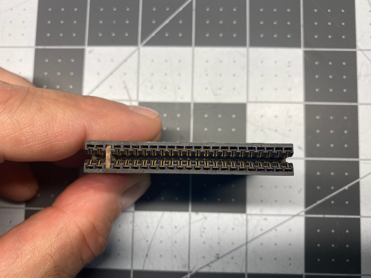
If you are looking to get some edge card connectors yourself, make sure to get ones that have a 0.100" pitch/width between adjacent contacts (I have seen some that have other pitches, and those would not work) and at least 23 contacts per row with two rows (top & bottom rows of contacts).
As can be seen from the image above, at least one end of the edge card connector needs to be open to fit onto the circuit board, but in order to fit the opening in the case of the computer, both sides need to be open. An example of this is the connector of Memotech's "Memopak 16k" RAM expansion.
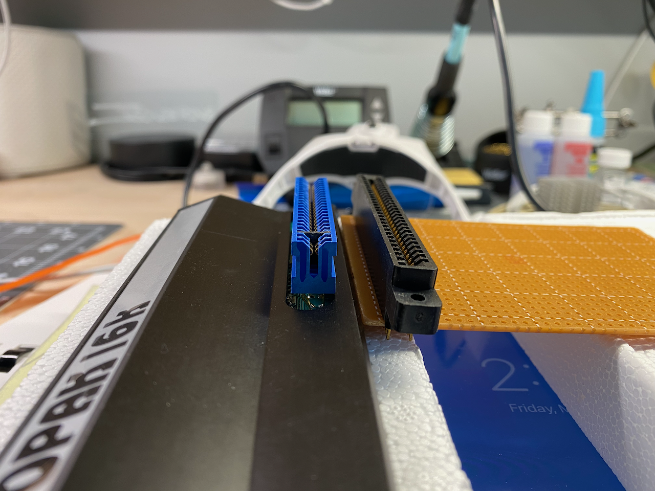
The only thing that I could think to do, and what I think Memotech did, was cut the ends off of a standard edge card connector...so out came the Dremel!
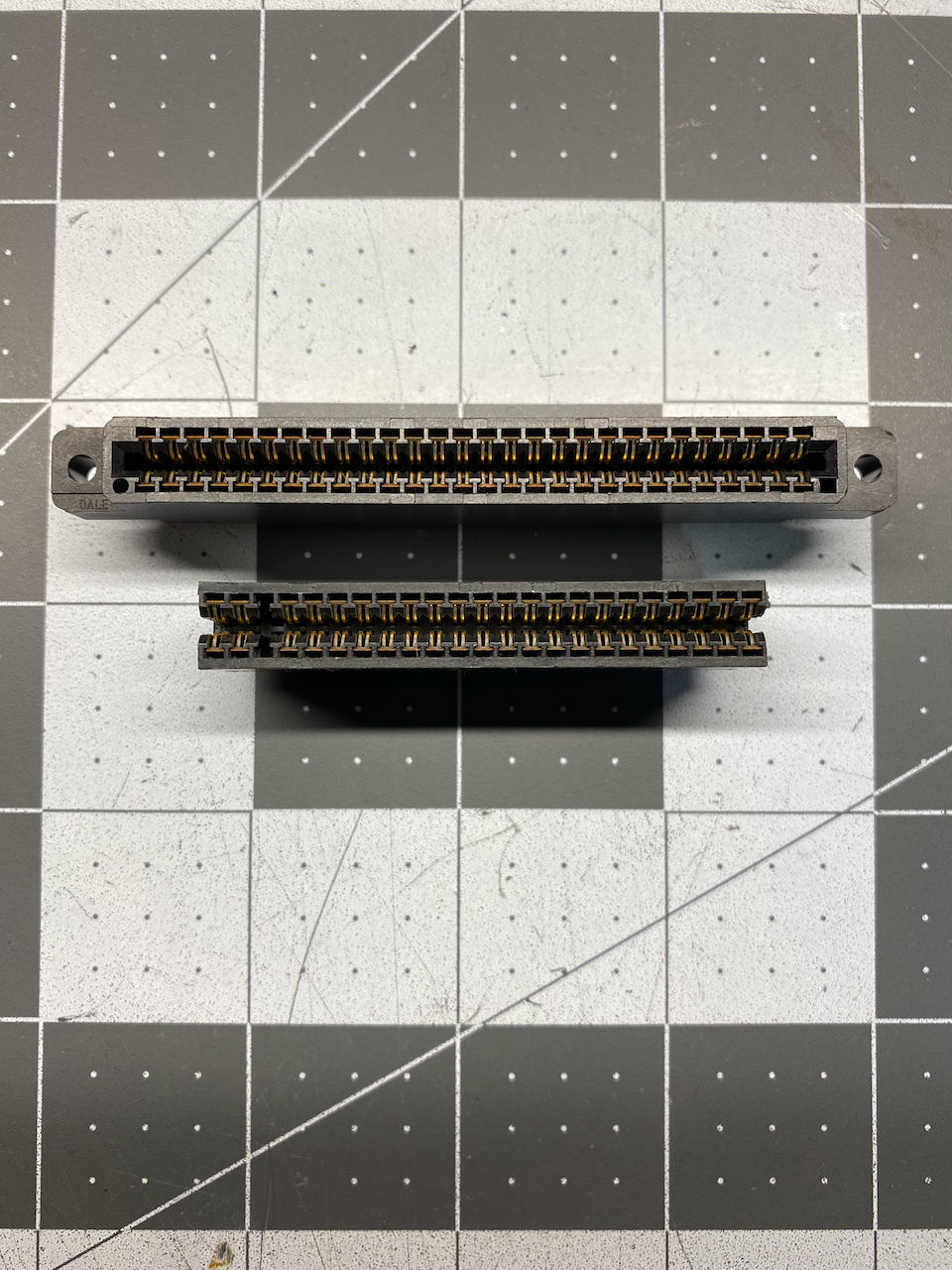
After carefully cutting the ends of the edge card connector with a Dremel and a cutoff wheel (a band saw would be ideal if you have access to one), I also pulled out the top and bottom contacts in the third column of the connector to make room for the "Keyway", a way to prevent connecting a peripheral the wrong way around.
For the "Keyway", as it is called in the ZX81 schematic legend of the edge card connection, I cut and shaped a scrap piece of circuit board to put inside the third column of the connector. The scrap piece of circuit board was actually from an old RF Modulator board that I removed from my TS-1000 when doing a composite video mod, as all of my other perfboards were too thick. Finding these keys is not impossible, but they are typically way too expensive. Some have claimed they are mostly made of a rare element known as "Unobtainium" 🤣
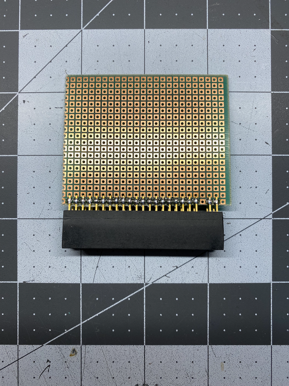
Next, I cut a piece of perfboard and soldered one row of pins to the solder pads on the bottom. I made sure to have the pins extend out to the next set of solder pads so that I would have added mechanical stability from double the number of solder connections on the perfboard. The other benefit of having the pins extend to the next row of solder pads is that it makes for a nice place to make the solder connections between the wires and the ends of the socket pins.
Next, I took a set of 90 degree male header pins and soldered them to the top row of the edge card connector pins, and then soldered the other ends to the solder pads on the bottom side of the perfboard.
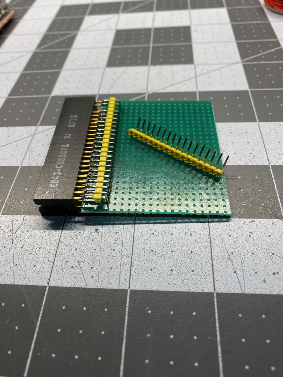
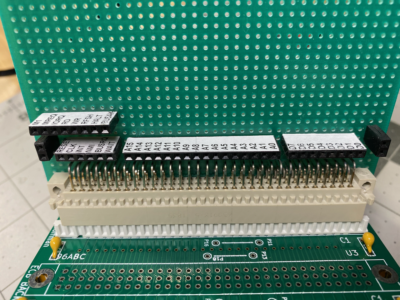
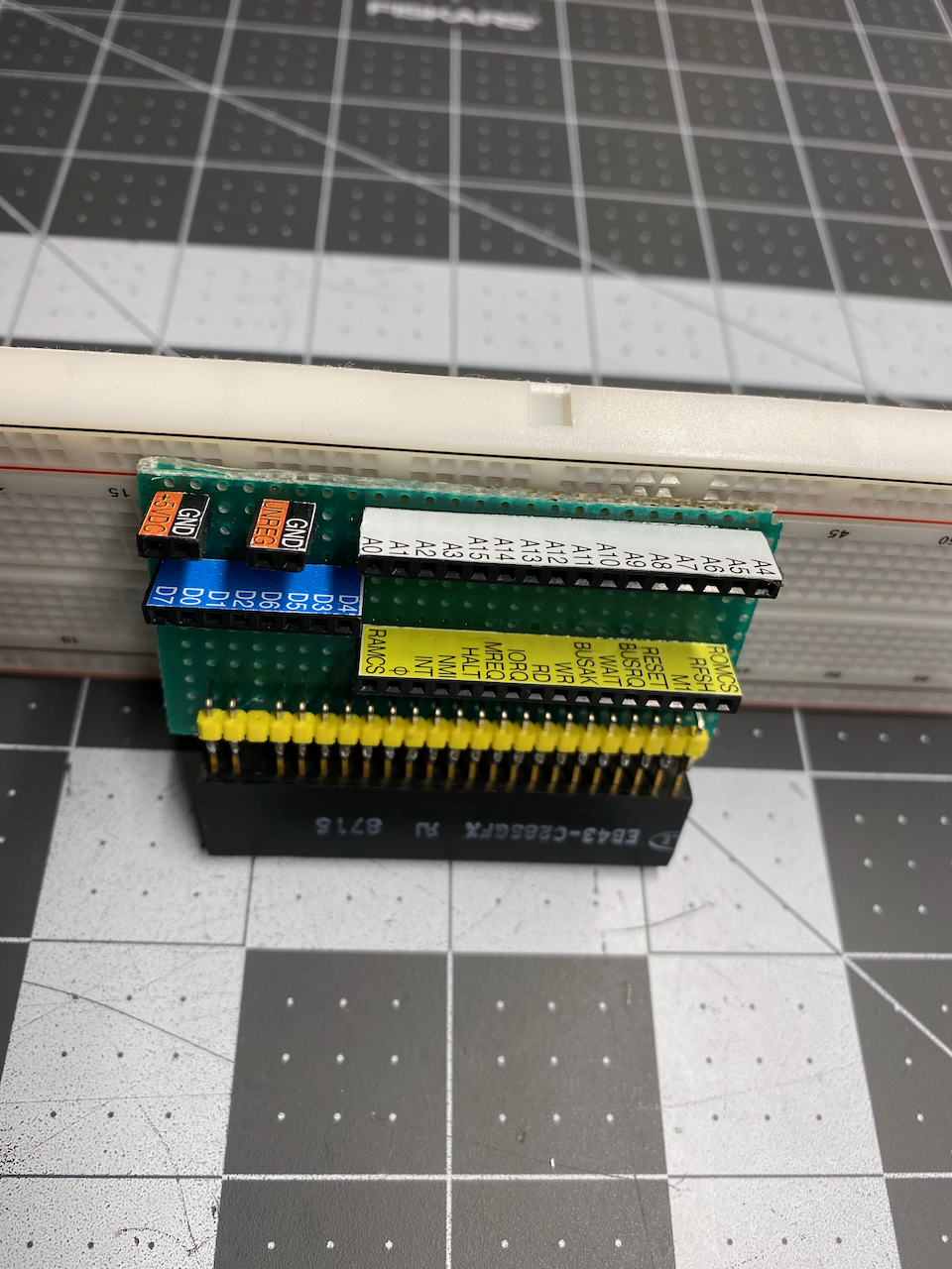
For the female breakout headers, I decided on a layout similar to what I did on my DIY 8 bit computer breakout board. I made one header for all of the control signals, one for the address bus, one for the data bus, and two "itsy bitsy" two pole headers, one for the +5VDC & Ground supply potential, and one for the unregulated 9-11VDC & Ground potential, and then I soldered them all onto the perfboard.
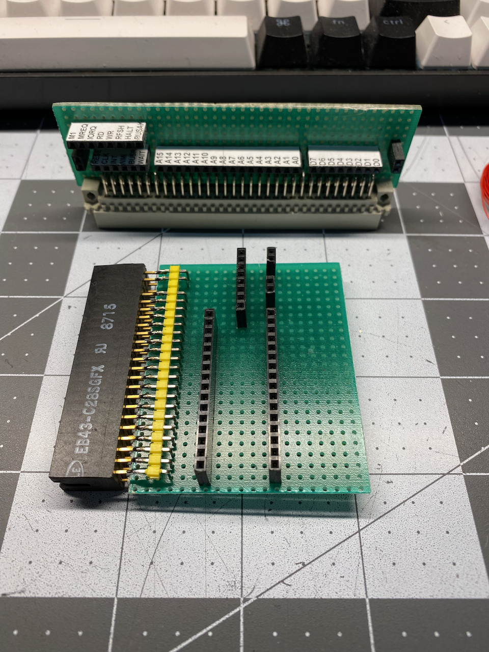
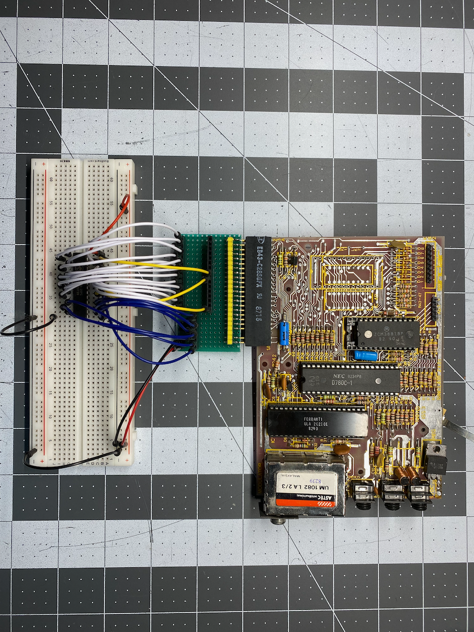
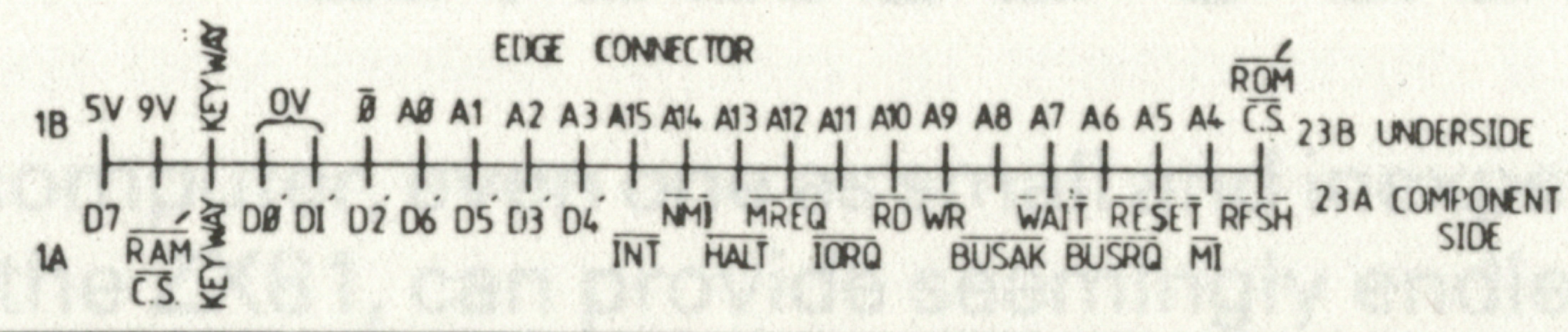
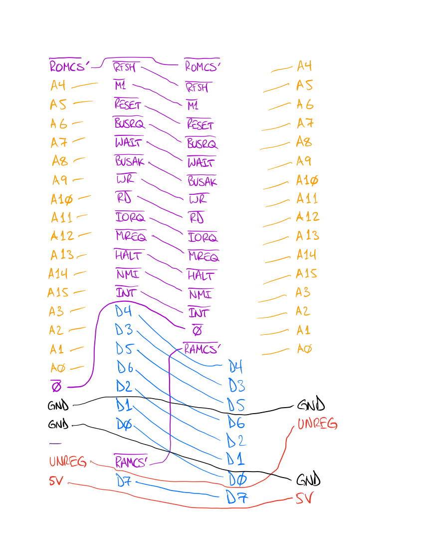
With the edge card connector/socket and all of the breakout headers soldered in, it was time to wire up all of the connections. Using the edge card legend from the ZX81 schematic as a guide, I made a sketch of the wiring from the two rows of pins coming off of the edge card connector to the five headers I had soldered in.
For this kind of thing, I prefer to use wire wrap wire because it is small and the insulation melts off fairly easily by simply rubbing the end of the wire against the tip of the soldering iron.
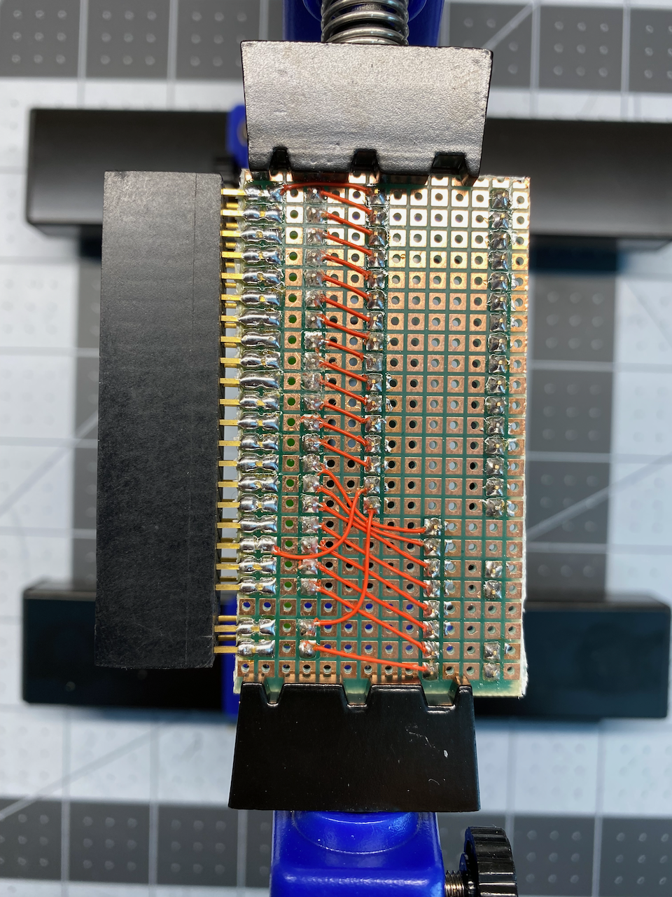
Since there were going to be wires going over the tops of other solder joints with limited space, and I wanted the wires to be just the right length, I made all of the inner connections first. All of the wires between the top row of edge card connector pins and any of the headers that they connect, with only two exceptions, the ROM Chip Select (ROMCS'), and the Clock signal (Ø), were soldered in the first pass.
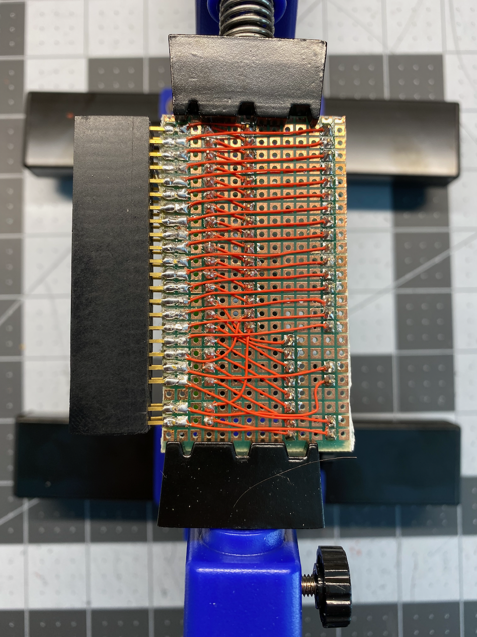
After all the inner connections of the first pass were soldered, I was able to make a second pass for the outer connections with ease and peace of mind, what more could you ask for!
Inkscape & Laser Printed Waterslide Decals
With all of the soldering done, it was time to go into my favorite open source vector image editing application (Inkscape) and make all the decals that I needed to apply to the female breakout headers. Inkscape has a bit of a learning curve because it does so many things, and the documentation or intuitiveness is sometimes lacking. But for free open source software, it can't be beat. Inkscape is also multi-platform, so it works on Linux, Mac OSX, & Windows.
Once I designed the decals in Inkscape, I printed them onto waterslide decal paper with a white backing that is specially made for laser printers (most waterslide decal paper has a clear backing, and some are made only for ink jet printers). See my ZX81/TIMEX-SINCLAIR 1000 Custom Mechanical Keyboard Prototype - Part 2 post for more about Inkscape and helpful tips on applying waterslide decals.
With the breakout board completed, I decided my first test was to finally desolder the 2k RAM (Random Access Memory) IC from the circuit board of my TS-1000 (I was going to do that anyway in preparation of an internal memory expansion modification at a later date), and then get one of my 32k static RAM chips on a breadboard connected via the breakout board.
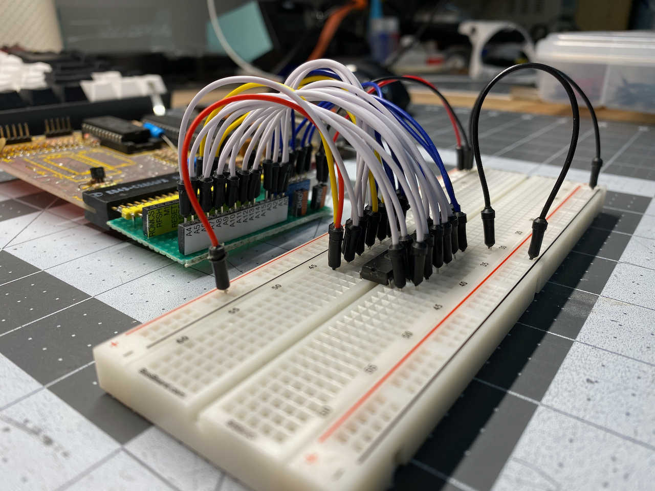
Without going into detail, the memory expansion via the breakout board was a success, and my TS-1000 was indicating 16k of RAM. I will make a separate post about modding a ZX81/TS-1000 to have at least 16k of RAM.
The prototyping I plan on doing for the memory expansion mod, as well as many other future projects, will be much easier with my new breakout board.