
ZX81/TIMEX-SINCLAIR 1000 Composite Video Mod Part 1
This is the first of a two part post that will start a series on modding the Sinclair ZX81 and the Timex-Sinclair 1000. The first mod being RF to composite video.

In this post, Part 1 of 2, I document one of a few different possibilities on how to convert the original RF video output signal from a TIMEX-SINCLAIR 1000 (hereafter TS-1000) micro computer to a composite video signal that can be viewed on a display with a composite video input. Part 2 of this post will document the conversion of an original ZX81 micro computer's RF output to a composite video signal. The difference in the two blog post parts is not so much due to a difference in the computer models themselves, but the versions of the Uncommitted Logic Array (hereinafter ULA) chips that could be inside of them.
Back in June 2021, I purchased an assortment of early computing nostalgia on ebay that reconnects me to the very first microcomputer I ever owned, the Sinclair ZX81. Not too long after the ZX81 was released, probably late 1981 or early 1982, my father purchased two ZX81 computers for my brother and me. Regrettably, neither of us kept our original ZX81 computers.
I was fortunate to find a ZX81 kit on Ebay back in April of 2020, from Zebra Systems, in Brooklyn, NY, which I mention on my About Me page. I am not sure if I want to build the kit or leave it in it's unbuilt state, so that is why I bought the assortment in June of 2021, to have things to tinker with🤓.
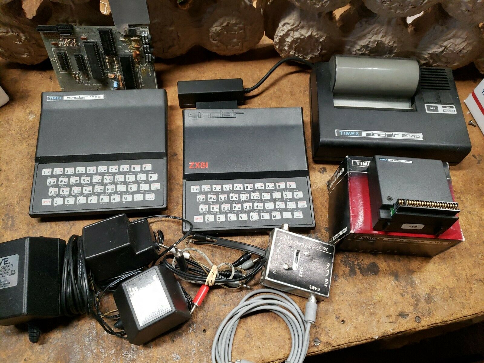
The assortment (pictured above) consisted of one ZX81, one TS-1000, a bare mainboard from a ZX81 (no case), one TIMEX-SINCLAIR 1016 16K RAM Module, one TIMEX-SINCLAIR 2040 Thermal Printer, an assortment of wall warts, a television switch box, and a few cables. The seller clearly stated that all of the items were untested, and since my sole intention for purchasing all of these goodies was nostalgic tinkering, untested was fine by me.
Once the package arrived, I boxed up the ZX81, the memory expansion module, the television switch box, a wall wart, and shipped them to my brother so he could tinker, too! The plan is to take these computers and mod them as far as possible just for fun. My plan is to write a series of blog posts documenting the various mods that my brother and I attempt in the hopes that it encourages others to get their old computers out of the attic and follow us down the retro computing rabbit hole.
ZX81/TS-1000 Original RF Video Output
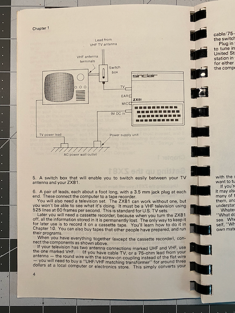
When the ZX81 and many other early personal micro computers were released, most of them did not include a dedicated display/monitor, most likely because computer monitors were not cheap back in the day! For that reason, many personal/home computers were built so that the average user could just connect the computer to a standard television set. Television sets back then could only get a signal into them via an aerial antenna or a cable television box. Computers of the day then had to use that same input on the television to get their video output to display. Many people that wanted to still use their televisions to watch their favorite shows could connect a switch box between the television and the computer's video out. The switch box allowed them to switch between the signal coming from the antenna on their roof and their computer.
Fortunately, I lucked out and found an older flat panel LCD monitor at a Goodwill store that has a plethora of video input signals, one of them being "antenna/cable in". I spliced a scrap composite cable with an old coaxial cable and tried tuning the monitor to the correct channel without success. The TS-1000 made for North America has a small switch on the bottom to switch between channels 2 & 3. I tried both switch positions with no sign of life from the monitor. I checked online for anyone else still trying to connect the RF signal straight to a monitor with an antenna connection, and I found two posts where others had to connect through another device. One person used a VHS player, and the other used a DVD player before connecting to the display to get something to work.
Since I only wanted to test the RF output for the sake of thoroughness, and for this blog, knowing good and well that I would only ever use the composite mod going forward, I decided to just gut the RF Modulator and start with the mod.
Two Mods for Two Different ULAs
In my online research on composite video modifications (See the Sources at the end of the post) there were a lot of YouTube videos and blog posts detailing how to do exactly what I wanted. One of the first things I saw from several different sources was that there are two versions of the ULA chip, and each requires a different mod as mentioned briefly in the introduction. I was pleasantly surprised to discover that the TS-1000 I have has the newer ULA 2C210E, and the ZX81 that my brother will be modding has the older ULA 2C184E, which means we will need to do both versions of the mod!
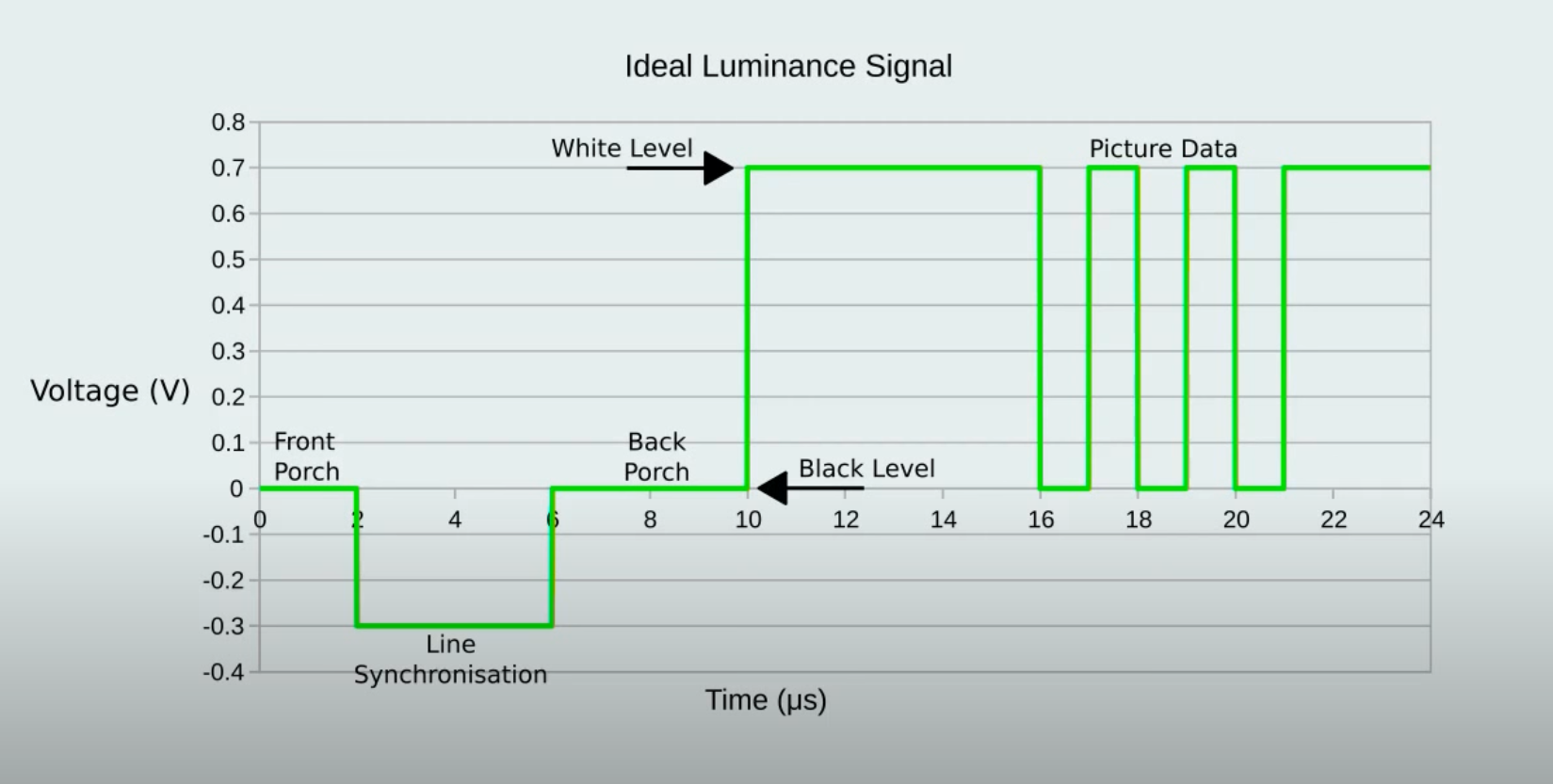
The major difference between the two ULAs is that the newer ULA creates a "back porch" in the video output where the older ULA does not. In order for a monitor to process the composite video signal coming from the modded computer there needs to be a "back porch".
So what does the back porch do, and why is it so important? The back porch occurs immediately after the horizontal line synchronization pulse, and lets the display know what voltage level should be used to display black. The back porch lasts about 4 microseconds and is followed by the picture data. In the case of the ZX81 and TS-1000, there is only black and white, so now that the display knows what voltage level is black, the other voltage level will have to be white, or full luminance.
Disclaimer:
I have no practical knowledge or experience with video electronics, I'm just a hobby tinkerer learning as I go. The information I am regurgitating here was presented by others who appear to have enough knowledge on the topic to prevent damage or injury. Any attempt to duplicate this modification is solely at the readers own risk. In addition, this is not a tutorial on working with electricity, electronics, or soldering.
Doing The Mod
As mentioned previously, I knew that I am only ever going to want to use composite video, and that I am planning on fully modding this computer, so keeping it stock is not a concern. The first thing to do will be gutting the RF Modulator, which has a lid that comes off very easily, but it's circuit board is soldered to the case from the bottom, and the case is soldered to the computers circuit board along with the three leads going into the RF Modulator. The modulators case is grounded to the ground plane of the circuit board to shield the video signal from interference. With all that metal from the case and the printed circuit boards (hereinafter pcb) ground plane soaking up the heat from your soldering iron, you will need either a larger iron, or a higher temperature setting, and some patience for the solder to melt.
After removing the modulator from the pcb the bottom cover of the modulator should come off just as easily as the top. Removing the bottom cover exposes the bottom of the modulators pcb, which is soldered to the modulator case in four places by a lot of solder. I didn't worry about being a bit rough with the modulators pcb since I was only going to dispose of it anyway. Lastly, there are components soldered to the case near the output jack and the output lead itself that need to be desoldered.
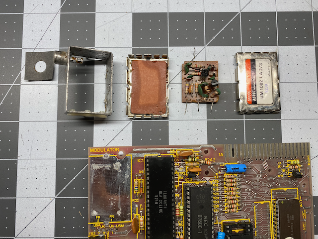
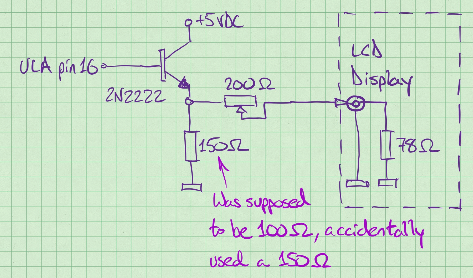
Following the basic direction of Timex Sinclair 1000 Part 1: Multi Region Composite Mod by Travis Durf, written specifically for a TS-1000 made for North America, I desoldered the channel 2-3 switch from the computer's pcb and then soldered in a bare solid AWG#22 wire as shown to always bring +5VDC up to the USA1 connection next to the modulator. Travis goes on to reuse the switch to allow the computer to switch between PAL & NTSC video output, but I did not bother doing that.
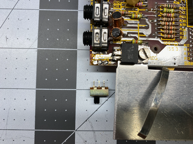

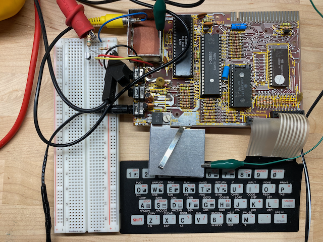
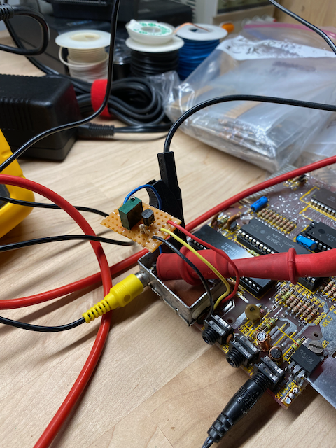
Before building the video output buffer circuit board adapted from ZX80/ZX81/TS1000 COMPOSITE VIDEO MODS by ByteDelight, and soldering it all up, I decided to prototype the circuit on a breadboard first and experiment a little with different components and observe the results. I cut four wires extra long in four different insulation colors and soldered them to the points on the computer pcb and to the output jack of the modulator case. I used blue as the composite out, yellow as the video out from pin 16 from the ULA - video in to the buffer, red for the +5VDC supply to the buffer, and black as 0VDC or ground potential. I first tried the component values in the blog post that I decided to use as a starting point, and although I got something to display on the screen, the voltage levels I was seeing on the oscilloscope seemed low and the image on the screen seemed to be dimmer than what I was hoping for.
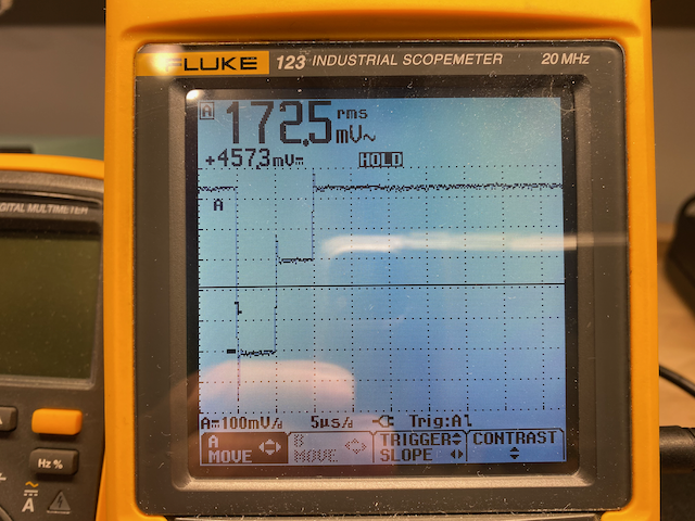
I was using a 3904 transistor from my parts bin, and I remember getting faulty transistors before on other projects, so I swapped it out for a 2222, a compatible alternative general purpose NPN transistor to the 3904. The signal was now much closer to what I was expecting and so was the display on the LCD monitor! Even though it has been a VERY long time since I first wrote BASIC programs on my ZX81 on a black and white CRT television set in the corner of our dining room, I immediately appreciated the difference in quality of the image.
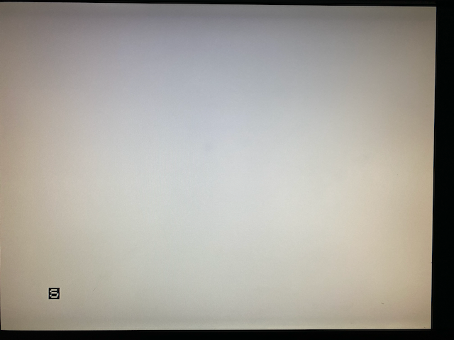
Normally the cursor should display a reverse video "K", but I was getting a reverse video "S". I believe that represents a Syntax Error prompt, but without having typed anything in, at that point I didn't even have a keyboard connected yet, and maybe that was the cause of the error prompt? I decided not to worry about that for the time being and soldier on to get the display mod finished, and look into the error prompt later.
I played around with various combinations of resistor values to fine tune the output and discovered that there really weren't any conventional resistor values that worked for an output that would give me a clean 1 to 1.2 VDC p-p. I did have a 200 Ohm variable resistor that I could wire in as a rheostat as the series output resistance, so I added that and adjusted the resistance until I had a nice image on the LCD monitor and a reasonable output signal voltage.
Once the prototyping was done, I cut a piece of perfboard and soldered everything on it still using the extra long wires for one final test before cutting everything to length and mounting into the modulator housing.
I realized after soldering everything on the perfboard that I accidentally got the 100 Ohm resistor swapped with a 150 Ohm resistor! It didn't make a noticeable difference, and rather than redoing everything I decided to leave it as is. I then cut all of the extra long wires, mounted the new buffer pcb into the modulator case and soldered everything permanently.
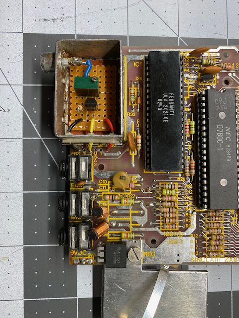
One final note, it wasn't necessary to put color coded insulation on the leads going into the modulator case to the buffer board, but my OCD likes the look, and the fact that it is an immediate visual cue to anyone looking at it of what each wire might be. There are plastic bushings that would insulate the wires from the grounded case, so the wires could have been installed bare - without insulation since the holes in those bushings are too small to fit the #22 AWG solid wire and insulation through. I could have drilled them out to a larger inner diameter, but decided instead to just use two pieces of insulation on either side of the bushings. I am happy with the appearance and function of the end result.
I connected the keyboard that came with this computer and the cursor returned to the expected reverse video "K". In Part 2 of this post we will build a composite mod for the older ULA that does not generate a back porch in its video output stream.
Sources
YouTube Video: ZX81 Video Conditioning by JoulesperCoulomb
Timex Sinclair 1000 Part 1: Multi Region Composite Mod by Travis Durf
ZX80/ZX81/TS1000 COMPOSITE VIDEO MODS by ByteDelight