
Atari 800 - Part 1

This is the first post in a series that I plan to publish chronicling a revival of my very first experiences programming in BASIC on an 8 bit Atari 800 computer. I plan to share what resources are available to anyone interested in getting started with Atari retro computing, or anyone also wishing to relive their early computing experiences with the Atari 8 bit machines. The plan is to dig much deeper into the hardware to feed my interest in digital electronics, and also to do some 6502/Atari assembly language programming, something I never got around to doing back in the day.
My Best Friend's First Micro Computer
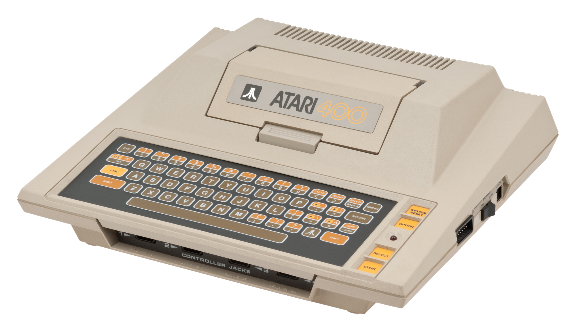
My very first experience programming computers came when my best friend's father purchased an Atari 400 with the 410 cassette drive for his son. It came with a BASIC (Beginners' All-purpose Symbolic Instruction Code) programming language cartridge, similar to the game cartridges used in the famous Atari 2600 game console. Soon we were learning how to write our own programs in BASIC, and specifically how to program graphics so we could make our own video games.
It wasn't long before my friend's dad upgraded him to the Atari 800 with the 810 floppy disk drive. The 800 used the same BASIC cartridge as the 400, but could accept more memory, could connect to a real monitor in addition to a color TV, and best of all it had a non-membrane "clicky" keyboard!
In March of 2021 I purchased an Atari 800, an 810 floppy drive, the power supplies, and some game controllers on eBay, from the original owner, knowing only that the power LEDs came on when plugged in. I was so excited when the package finally arrived only to be bummed out to see that there was shipping damage to the 810 floppy drive. I informed the seller of the damage after having already sourced most of the replacement parts from another Ebayer. The seller graciously offered to refund whatever the repair parts would cost.
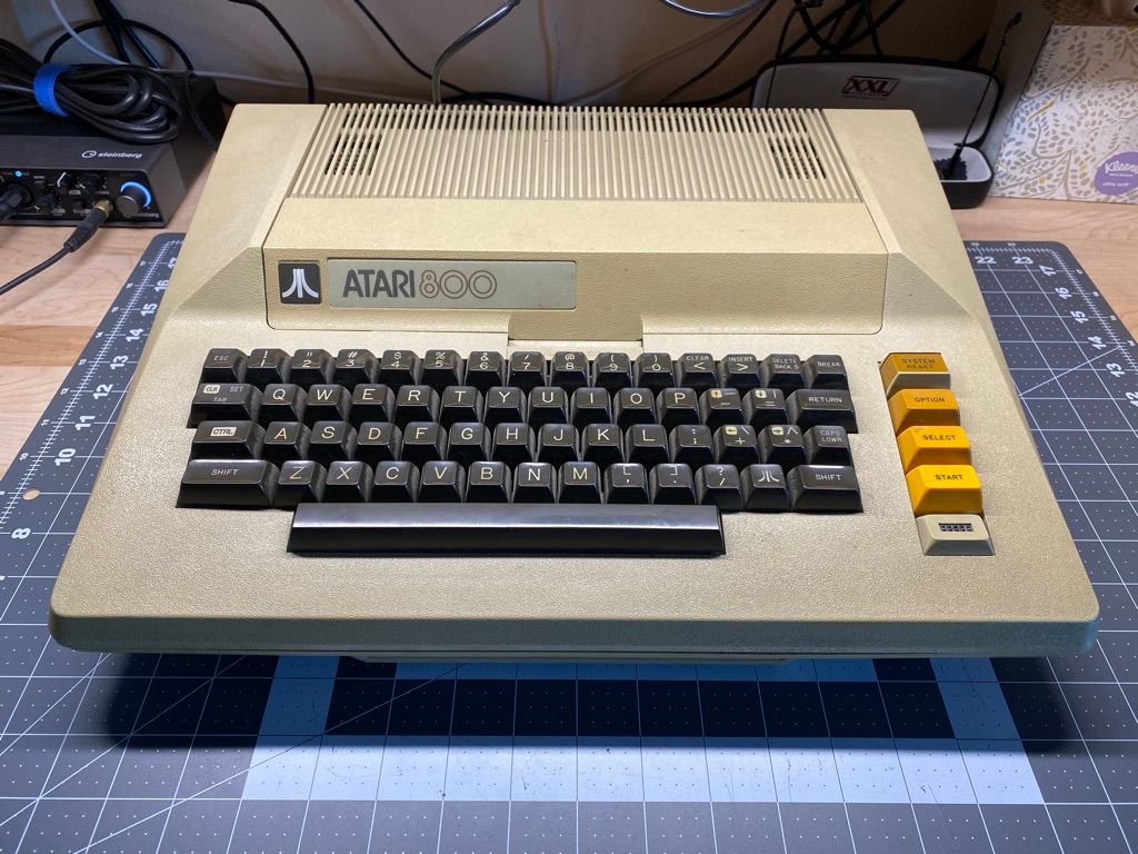
Even though the seller had recently plugged both the 800 and the 810 into power for the photos to show that the power LEDs come on, I didn't want to power up the computer until I had opened it up and given it a thorough inspection. Before the computer shipped, I had already downloaded the Atari 400-800 System Service Manual 1981-04 from the Internet Archive so I would know how to safely open and disassemble it.
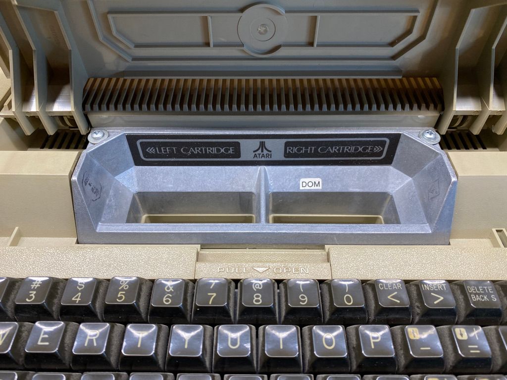
The computer was sold without any cartridges, so there was no surprise when I opened the cartridge door to both the left and right side cartridge slots empty. I knew from the sellers photos before purchasing the computer that the original cartridge door clamps were missing, and had been replaced with simple screws and flat washers.
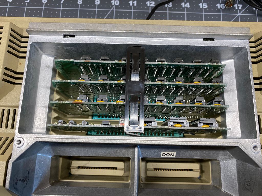
After removing the aftermarket screws and flat washers, I slid the cartridge door assembly slightly up and forward to clear the tabs in the back and lifted the assembly away, revealing the three 16k RAM (Random Access Memory) cards, and the ROM (Read Only Memory) board, A.K.A. "Personality Board". The tops of the boards were somewhat secured with a spacer made of plastic, preventing the tops of the memory boards from wiggling around.
I removed the memory boards and flipped the computer upside down to remove the five Phillips head screws that hold the top and bottom case halves together revealing the speaker, the bottom of the RF Shielding around the motherboard, & the bottom of the power supply board. So far only very slight signs of dirt and dust, no oxidation, and no visible internal mechanical or electrical damage. Next, the speaker could be removed simply by disconnecting the plug from the power supply board header and lifting it out of its pocket in the upper housing.
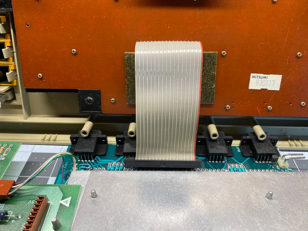
There are three Phillips head screws securing the motherboard & power supply to the upper housing, after removing them I carefully pivoted the combined boards and RF shield housing away from the upper housing exposing the connection of the keyboard ribbon cable to the motherboard keyboard header, and disconnected the ribbon cable.
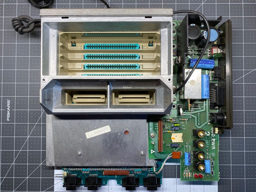
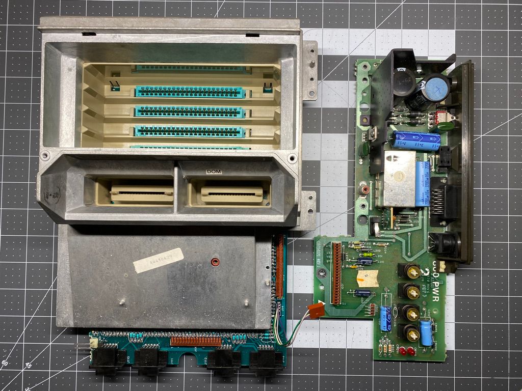
I knew that I was not going to ever connect the computer to a color television set via the antenna connection, so I proceeded to remove the RF cable and put it away. Three Phillips head screws mount the power supply board to the RF shielding of the motherboard, and the electrical connections are via a four pin header and a larger 22 pin header. After removing the screws and disconnecting the four pin cable I carefully separated the power supply board from the motherboard.
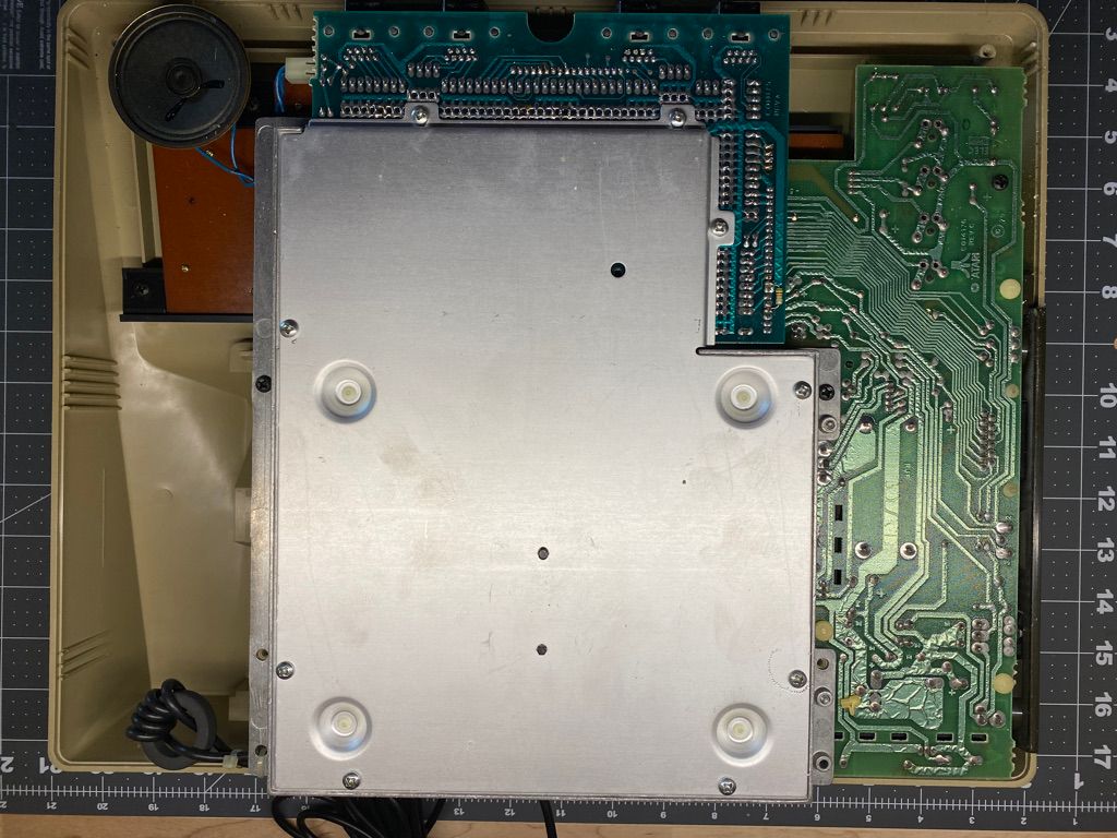
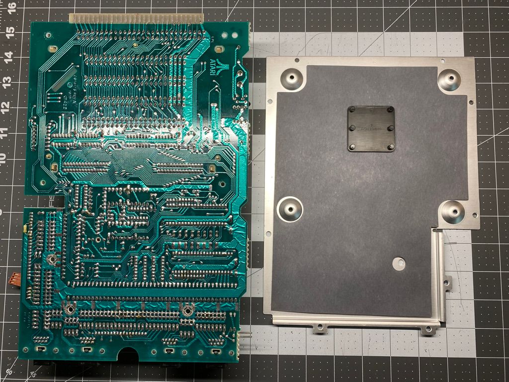
With the motherboard and power supply boards separated, I flipped the motherboard upside down and removed the nine Phillips head screws securing the RF shield housing together and carefully lifted the bottom RF shield plate together with the motherboard out of the top casting.
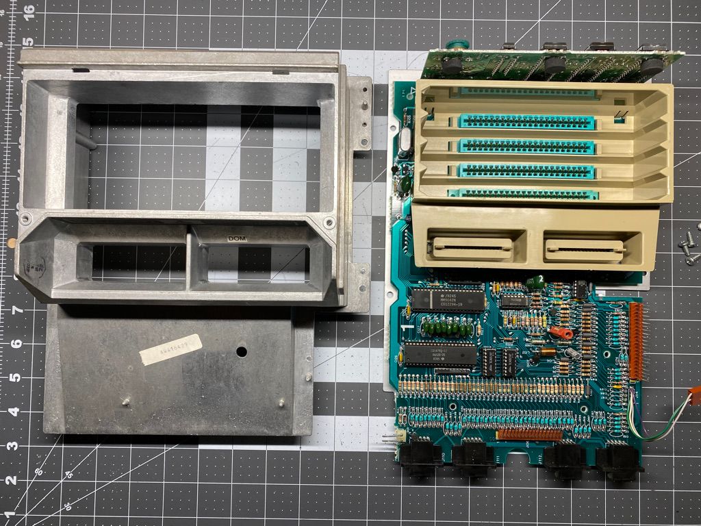
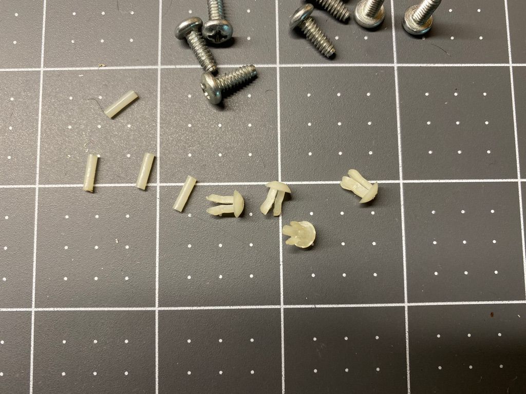
Once out of the casting, the CPU board was exposed and could be removed from the motherboard. There are four nylon clips with pins inside that lock the bottom RF shield plate to the motherboard. Using a fine point tool the pins can be pushed out the bottom allowing the four petals of the nylon clips to compress and slip out of the holes in the motherboard. Once all four have been removed the motherboard and shield can be separated.
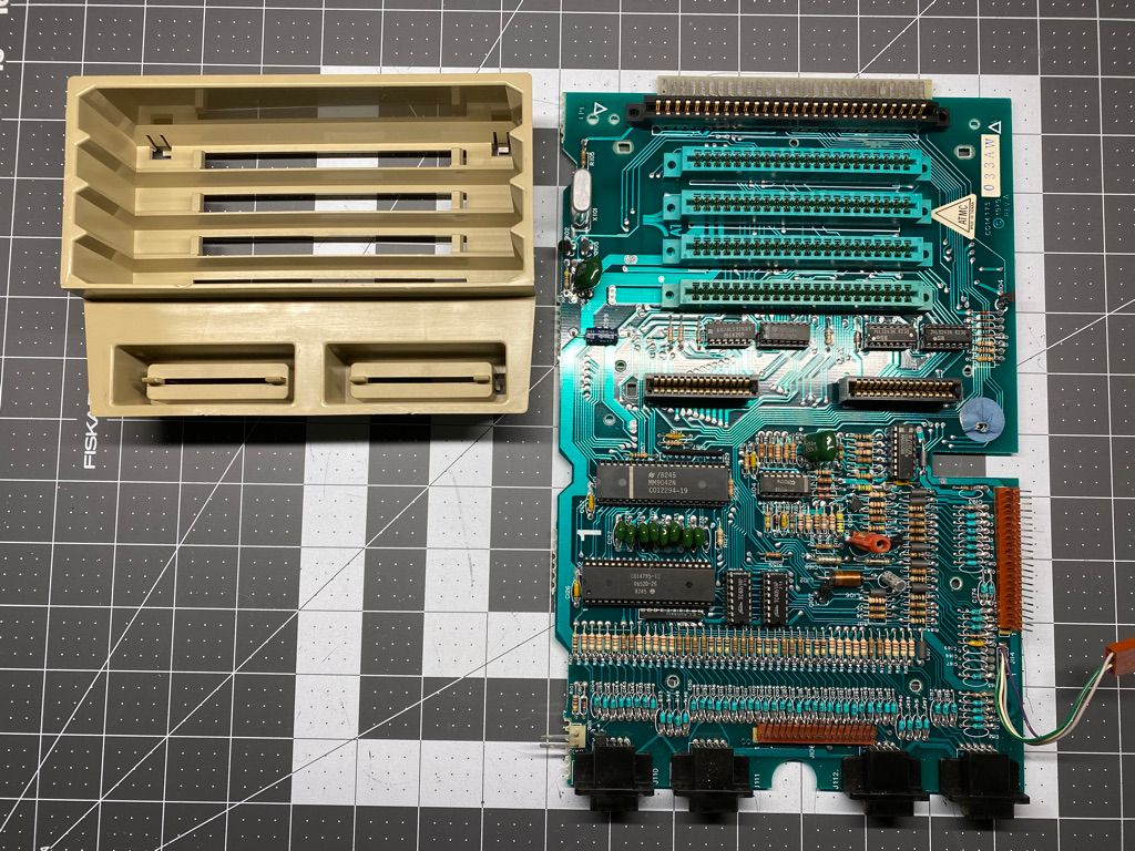
Lastly, the plastic cartridge guide can be separated from the motherboard by gently pushing the four clips with your finger. The disassembly is complete.
Now with the computer fully disassembled I had absolute power to do with it as I pleased! Most electronics contain one or more electrolytic capacitors, which go bad over long periods of not being powered up. The Atari 800 is no exception, and according to the seller, this computer has been in a box for 30 - 35 years! Before I was going to power it up I would first check all of the electrolytic capacitors and replace any that read marginally.
In Part 2 of this series I cover the testing of the capacitors in circuit, connecting the 800 to an LCD monitor, repairs to a malfunctioning keyboard.