
PLD Series - Part 1 - Programmed My First GAL

This is the first post in a series I plan to write on Programmable Logic Devices (PLD). By following this series the reader should get a basic understanding of the different types of PLDs and how to start using them in their own projects. This post will cover the basics of programming and testing a GAL (Generic Array Logic), one of the earlier types of PLDs which as of this writing, are still being manufactured. For a detailed history of PLDs and the various types follow this link to Wikipedia.
I first recognized what PLDs were a little over a year ago while looking into how to make a custom VGA (Video Graphics Array) display adapter/circuit for my custom 8 bit retro computer. I had seen acronyms like CPLD, and FPGA all over the place while shopping for electronics components and watching YouTube videos, but never felt the need to look into what they were. In my search for how to make my own VGA adapter, I recall watching a very informative video series on YouTube by Ben Eater titled, "The Worlds Worst Video Card?".
Ben Eater built his video card with off-the-shelf TTL (Transistor-Transistor Logic) ICs (Integrated Circuits), but I was also seeing solutions out there that used PLDs, mostly CPLDs (Complex Programmable Logic Devices) and FPGAs (Field Programmable Gate Array).
Firstly, for the video display I wanted to use as basic a type of PLD as I could get away with, like PALs (Programmable Array Logic) or GALs. Secondly, CPLDs and FPGAs were not around in the early 80's (Neither was VGA, but that is another topic) and would not be true to the "retro" spirit of my custom 8 bit retro computer. From what I was seeing, PALs appeared to be harder to source than GALs, I believe that Microchip is the only manufacturer still producing GALs. So I ordered some Atmel (Atmel was purchased by Microchip) ATF22V10C-10PU GALs from an online electronics parts distributor and they sat in my parts bin for about a year, until last weekend. Last year was a busy year developing a custom job tracking web application for a customer on the East coast, but with that mostly done, I could start to play with my first GAL!
GAL Programming Basics
GALs are programmable chips containing fuses that can be set in a way similar to how non-volatile memories like EEPROMs are programmed. The difference is that your programming device will most likely need a file saved in a certain format, called a JEDEC file so that it knows which fuses to open or leave closed.
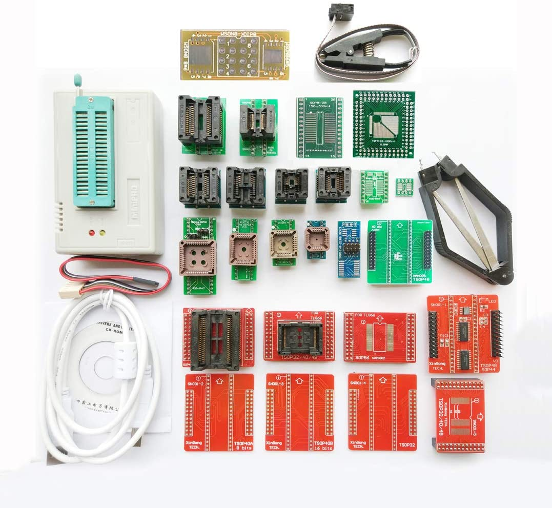
I used a TL866 II+ Universal programmer to program my GAL after creating the JEDEC file. The JEDEC file is a text file that could be created in a text editor, but I would not recommend it. From what I have learned so far, there is a free application that Microchip provides that runs in Windows called WinCUPL, and an open source GAL assembler called GALasm on GitHub.
I decided to try GALasm first because I could compile it on my MacBook Pro and run it from the command line. 🤓 In order to have GALasm generate a JEDEC fuse file, one must first create a text file with a .pld file extension. I created the following file which creates two input pins named A & B and six output pins named U, V, W, X, Y, & Z:
GAL22V10 ; The device type
gal-test ; The signature

; Pin definitions:
;   1st line: Pins 1 - 12
;   2nd line: Pins 13 - 24

A   B   NC  NC  NC  NC  NC  NC  NC  NC  NC  GND
NC  NC  NC  NC  NC  Z   Y   X   W   V   U   VCC

; Logic equations

U = /A
V = A + B
W = A * B
/X = A * B
/Y = A + B
Z = /A * B + A * /B

DESCRIPTION:
This file creates the following gates with
only the two inputs A and B:
    U = NOT (only uses A)
    V = OR
    W = AND
    X = NAND
    Y = NOR
Z = XOREach output pins logic level is determined by the input logic levels being fed into them, and that output's logic function. Looking at the six formulas and then the "DESCRIPTION" section, togther with a basic understanding of Boolean logic, one can see the next step was to let GALasm do it's thing...
GALasm ./gal-test.pldGALasm generates four files, one of which is the .jed file, the JEDEC fuse file! After inserting an ATF22V10C-10PU into the TL866 II+ ZIF socket, I used the open source minipro program from GitLab to burn the newly created gal-test.jed onto the chip:
minipro -p ATF22V10C -w gal-test.jed -PThere were some warning messages, but it appeared to have worked. I plan on digging deeper in following posts in this GAL series to find out how to get rid of the warnings and failed verification.
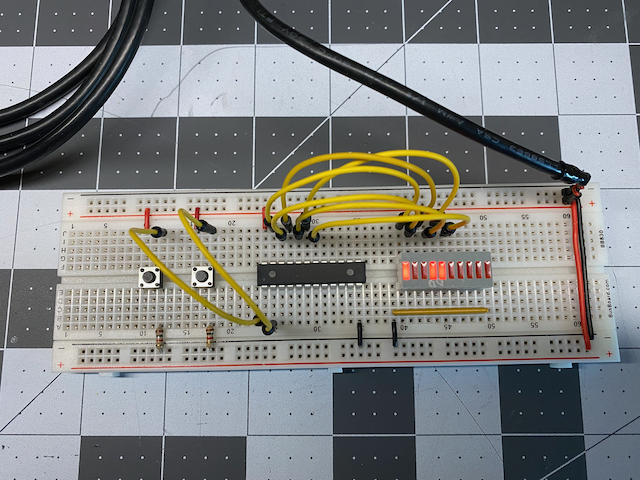
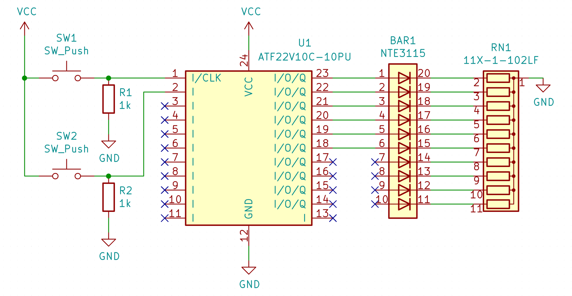
I removed the chip from the programmer and stuck it on a breadboard with two pushbutton switches and a bar graph LED array as per this schematic:
This is what it looks like:

Pushing the push button switches makes the input pins (A & B) of the GAL change from a logic "low", or zero Volts, to a logic "high", or five Volts, and the corresponding output pins of the GAL follow the programmed basic logic functions for the following gates: NOT, OR, AND, NAND, NOR, XOR. The first experiment was a success!
Stay tuned for more in this GAL Series.