DIY 8 Bit Computer Series - Part 2

In this second post chronicling the design and build of an 8 bit microcomputer from scratch, the resistors that were previously being used to simulate a memory are replaced with an actual memory chip.
Although there are modern options available for programmable memories that are much easier to program and erase, I wanted to see what it was like to work with earlier types of memory chips, and that is the main drive in this post. I also implement a version of Ben Eater's Arduino EEPROM programmer to read an EPROM.
Faking A Memory
When I first started playing with the Z80 microprocessor (see Part 1 of this series), I followed the lead of Julian Ilett from his YouTube video titled, "Flashing LEDs - Z80 Style".
In that video, Julian uses resistors to individually "pull-up" or "pull-down" certain control input pins and also the single bits of the data bus pins of the Z80 microprocessor. Pulling down the data bus pins simulates a memory device filled with NOP (No OPeration) instructions at every address.
NOP instructions do just that, NOTHING. There is nothing to execute, no other values to fetch from memory or another register, and no computation or altering of a value in the accumulator. The NOP instruction of the Z80 microprocessor is eight bits of zeroes - 00000000 in binary, and 00 in hexadecimal.
Using eight "pull-down" resistors to set each bit of the Z80's data bus pins to zeroes is a clever way to simplify a test circuit for the processor, thereby allowing the microprocessor to cycle through instruction fetch cycles and also incrementing it's PC (Program Counter) register and put the changing address values out on it's address bus pins.
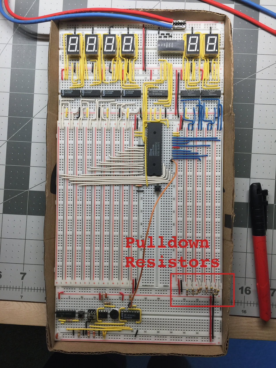
One important thing to note is that by using resistors instead of just wiring the data bus pins directly to ground or Vcc, we are protecting the microprocessor's data bus pins from a short circuit, should the processor try to write to the data bus at some point.
This setup completely disregards any address being placed on the address bus by the Z80, so regardless of what address the Z80 wants to read from, the value it will read will be zero.
Time To Stop Faking It
After thoroughly learning and understanding the sequence of steps the Z80 has to go through to perform a fetch cycle, I was done running NOPs and ready to execute more of the instructions that the processor is capable of. It was time to attach an actual memory chip to the address and data bus. Sure, I could have changed some of the "pull-down" resistors into "pull-up" resistors to simulate instructions other than NOPs, but that would have been tedious.
I was faced with the decision of whether or not to use a modern EEPROM (Electrically Erasable Programmable Read Only Memory), or an older style EPROM (Erasable Programmable Read Only Memory). I always want to get as much exposure to retro technology as possible, and since I happen to be building a retro 8 bit microcomputer, why not learn to work with the older style EPROMs first? 🤓
ROMs, & PROMs, & EPROMs... Oh My!
ROM (Read Only Memory) memories are manufactured to contain fixed data at each addressable location in the memory. In other words, the data on a ROM memory cannot be changed once it has been created. Making a ROM is an expensive process, and only makes sense when doing very large quantities. ROMs are great when information or instructions need to be available to the system right at startup, without loading it in from somewhere else first. The downside of ROMs is that the data on them cannot be changed once manufactured.
PROM (Programmable Read Only Memory) memories are manufactured to be programmed once, also known as OTP (One Time Programmable). PROMs come blank from the manufacturer to be electrically programmed by the end user in a device which permanently changes the internal circuitry of the device. Once programmed, a PROM essentially becomes a ROM, and cannot be written to again.
EPROM (Erasable Programmable Read Only Memory) memories are manufactured to be electrically programmed like PROMs, but unlike PROMs, EPROMs have a transparent window over the silicon chip which makes it possible to erase the chip by exposing it to ultraviolet light! EPROMs are perfect for development because it is fairly easy to try out a program and if changes need to be made, or bugs need to be fixed, the same memory can be reprogrammed by exposing the chip to UV light for a certain amount of time.
For quite some time now, EEPROMs (Electrically Erasable Programmable Read Only Memory) have been accessible. In EEPROMs the memory no longer needs to be exposed to UV light to be erased, but can be electrically erased in basically the same way that it is programmed.
As mentioned earlier in this post, using an EEPROM would be easier for me to use on my breadboard Z80 computer, but I wanted to get a taste of what it was like before EEPROMs were available... I really wanted to start with an EPROM.
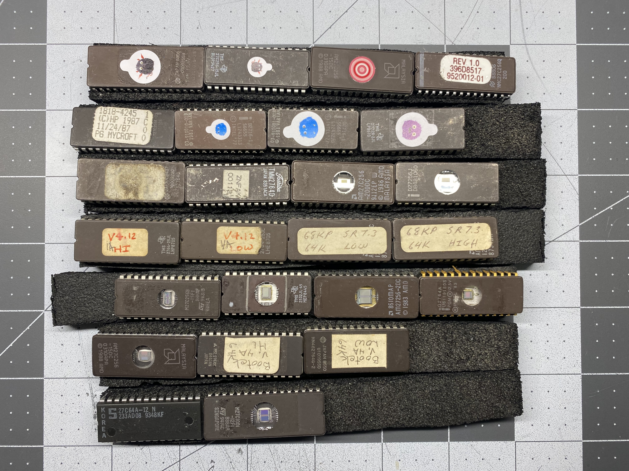
A good friend of mine, who is extremely knowledgeable in electronics, and also a pinball machine aficionado, was kind enough to send me a bunch of random EEPROMs he had lying around. Using upcycled EPROMs was more fun and interesting than buying new blanks. The used chips might still have data on them, and some might even have programs intended for a Z80!
Reading An EPROM With An Arduino
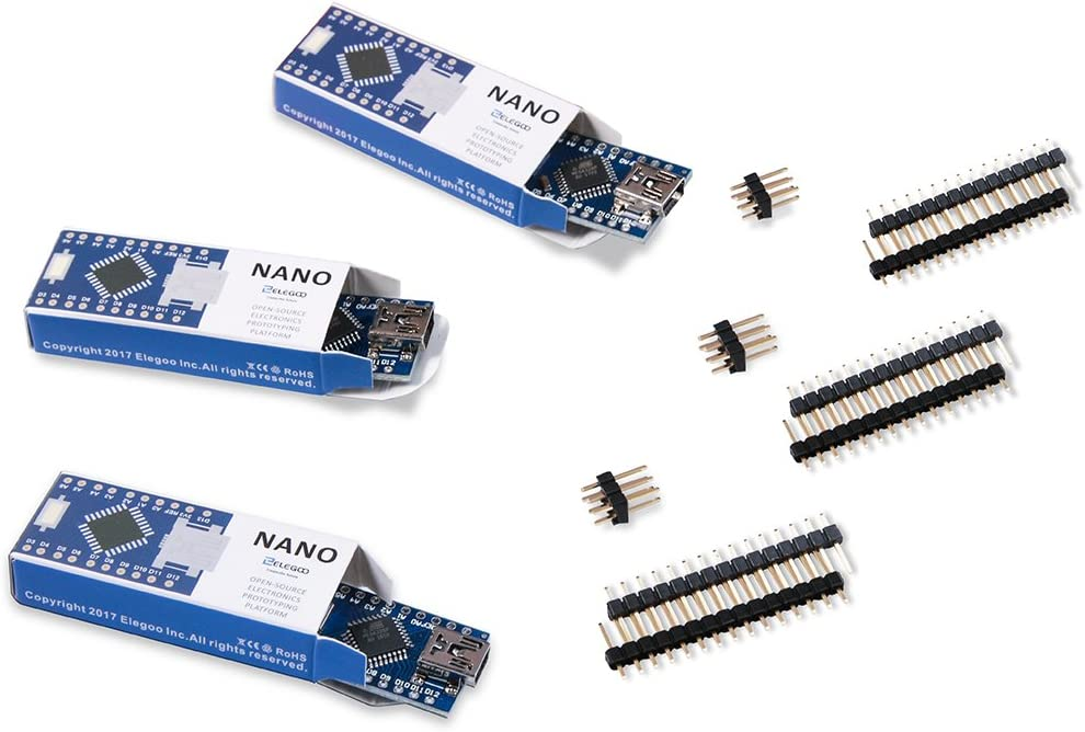
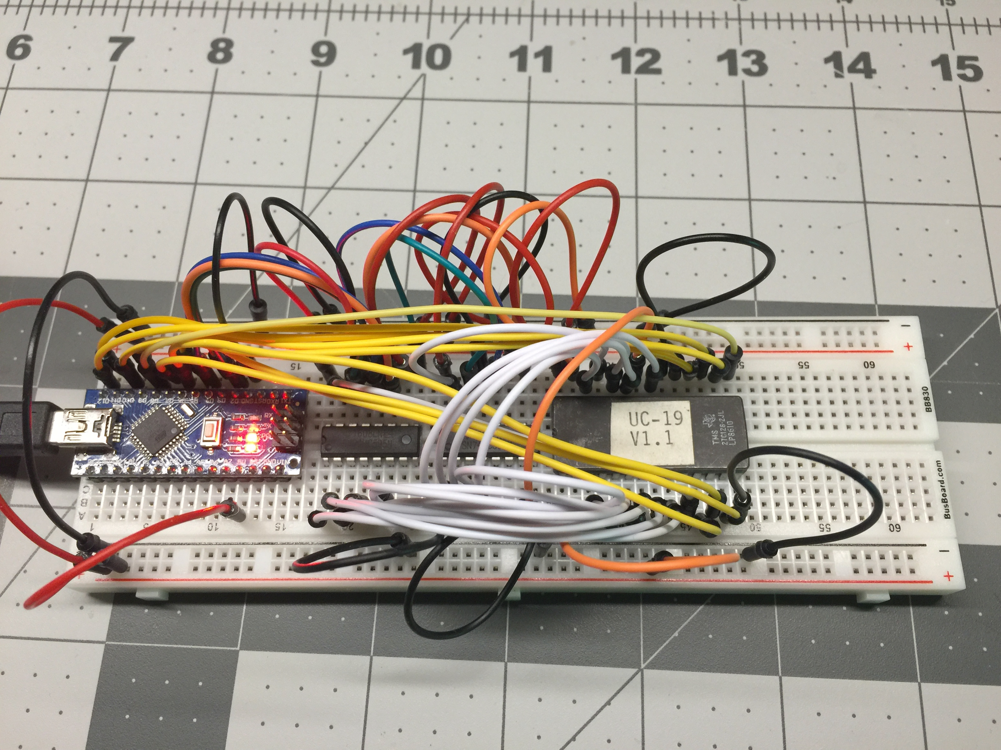
There are many good EPROM programmers out there to purchase these days (I did eventually purchase a TL866II+), and there are also a plethora of EPROM erasers available. At the time that I was starting out with this project (back in 2018), I wasn't sure whether I would need to pull the trigger on either just yet, and was still doing some research and shopping around. While researching and thinking about EPROM programmers and erasers, I was also watching a lot of Ben Eater's YouTube videos, one of which Ben walks us through building a DIY EEPROM programmer with an Arduino Nano. BTW: There is even a GitHub repository for the programmer at beneater/eeprom-programmer.
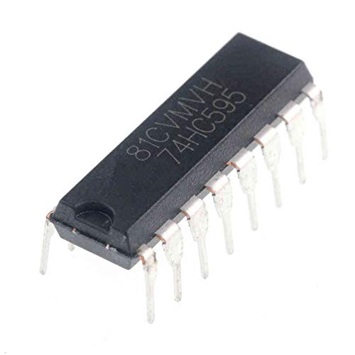
Wanting to follow Ben's lead, I purchased some Arduino Nanos, and some shift register ICs on Amazon. Following Ben's video, I built the programmer on a breadboard using one Ardiuno Nano and two shift registers. Once the programmer itself was all wired up and programmed, I needed to get my hands on a datasheet for the TMS27C128 EPROM, so I would know how to connect the EPROM to the programmer. The TMS27C128 is the EPROM that I chose from my used assortment. I was able to read the content of that EPROM on my laptop in no time!
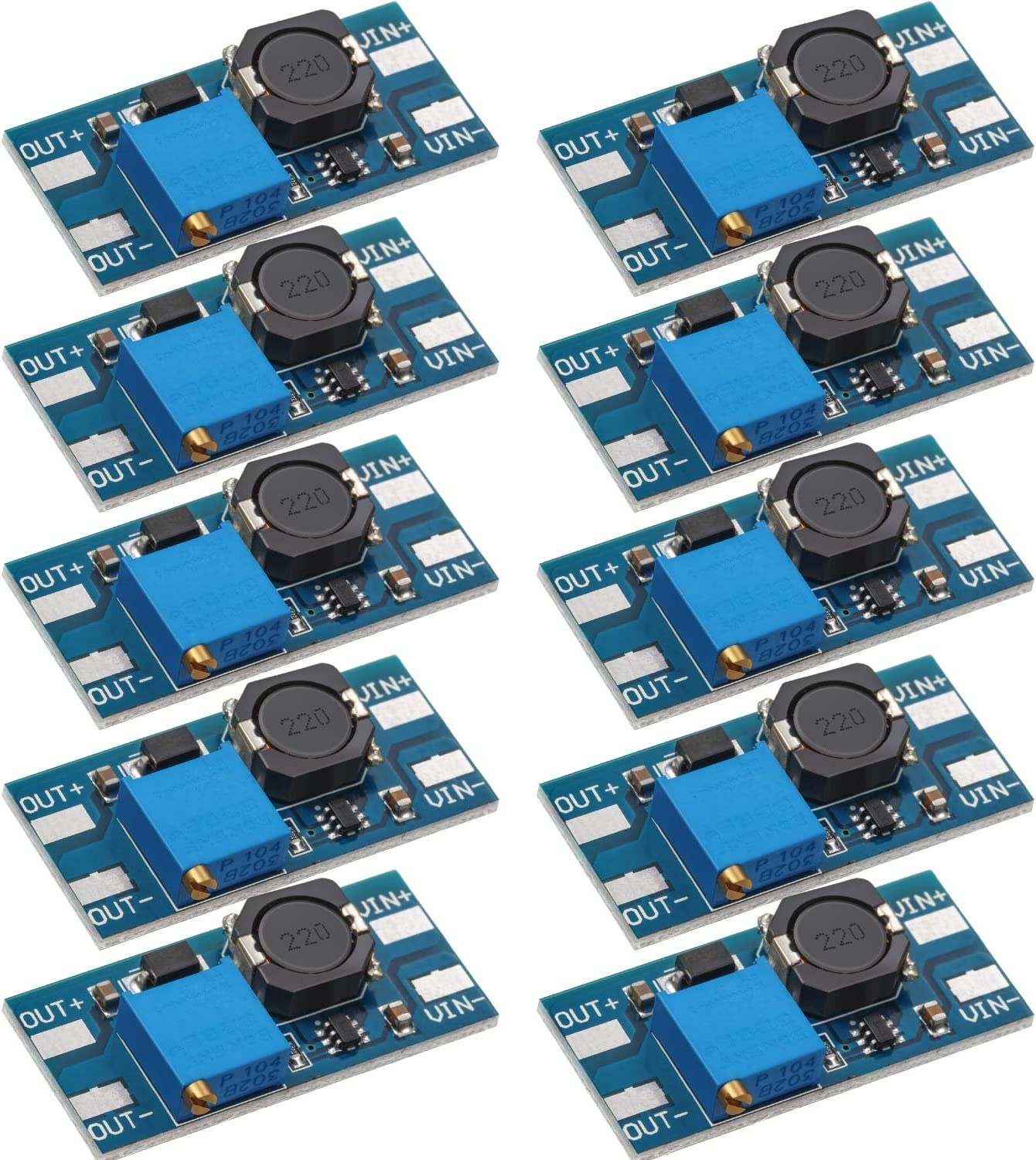
In Ben Eater's video, he used an EEPROM which does not require any voltages higher than 5 VDC. The EPROMs that I may eventually want to program require a programming voltage of anywhere from 12 VDC to 15 VDC. For that reason, I purchased a pack of boost converters from Amazon. Boost converters can take the 5 VDC on the programmer power supply and boost it up to the 12 or more Volts needed at the Vpp (Programming Power Supply) pin of the EPROM. Sadly, I never got around to connecting the boost converter to my build of the Arduino EEPROM programmer. Maybe that will be a future project and post? 🤓
Erasing EPROMs Without An EPROM Eraser
Now that I'd acquired everything I thought I would need to read and write to an EPROM, I knew that I'd need to be able to erase an EPROM before writing to it. I didn't foresee myself erasing a lot of EPROMs after I was done tinkering around, so I didn't want to invest in a legitimate EPROM eraser. So I looked around for something less expensive that contained a UV light source and was large enough to contain a 28 pin DIP (Dual Inline Pin) package. A decent (reviewed & vetted) EPROM eraser will set you back over $100, which is not unreasonable. Recently I've seen UV erasers for less than $40, but they have very few reviews, and who knows how reliable they might be?
In late 2018, I found an inexpensive dental cleaning case for a little over $40 on Amazon, and wondered if it would erase an EPROM... What I liked was how small and portable it was, and that it ran on batteries.
The dental cleaning unit did work, although one annoying thing about it was that it has a built in shut-off timer that cannot be adjusted. I also remember not getting a full erasure in one cycle. It took two passes to fully erase one sample EPROM. I figured at a later date I might choose to disassemble it and disable the timer, or make it so that I can set the time, but never got around to it...
Connecting The EPROM To The Data Bus
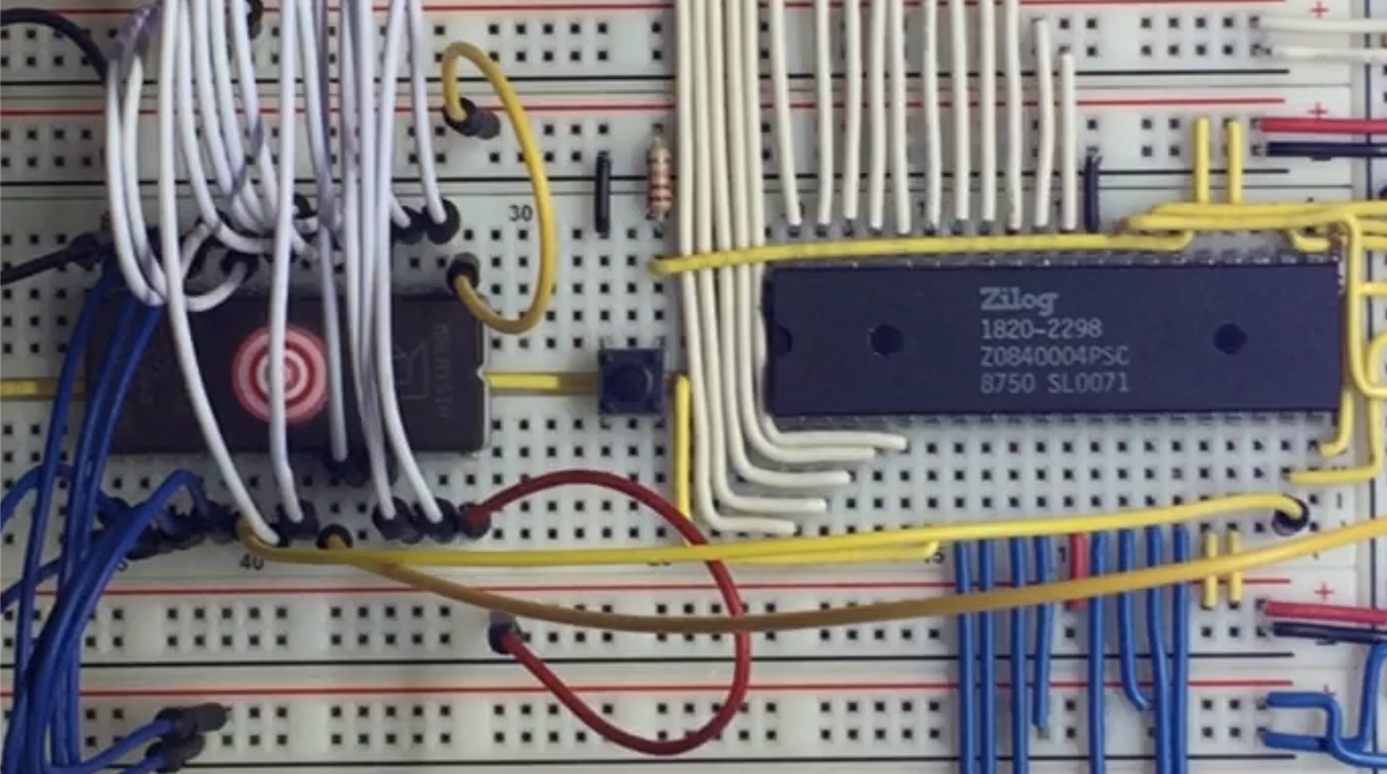
The first thing I had to do was remove the pull down resistors from the data bus before connecting the EPROM. For some reason, I cannot remember why now, but I changed EPROMs, so instead of the TMS27C128 that I originally started playing with, I switched to an AM27C256. Using the pinout and description from the datasheet that I downloaded for the new EPROM, I connected it to the Z80.
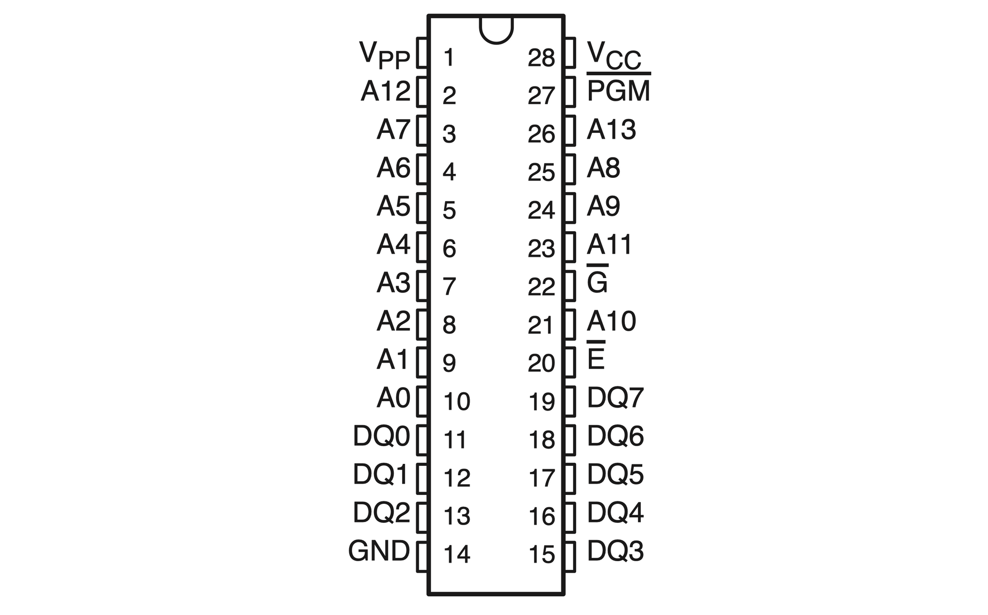
What is really interesting is that both EPROMs come in a 28 pin DIP package, so both have the same number of pins, but the AMD AM27C256 has double the memory size. The last three digits in the part numbers are kilo-bits, not kilobytes. So the 27C128 contains 16 kilobytes (128 kilobits divided by 8 bits/byte equals 16 kilobytes) of memory, and the 27C256 contains 32 kilobytes of memory. In fact all the pinouts are identical except for pin 27, which is labeled /PGM on the 27C128, and A14 on the 27C256. Adding another address pin makes sense to address double the number of memory locations, and in the case of the 27C128, the /PGM pin is a special pin for Texas Instruments "Snap! Pulse Programming" algorithm, which I will not get into here.
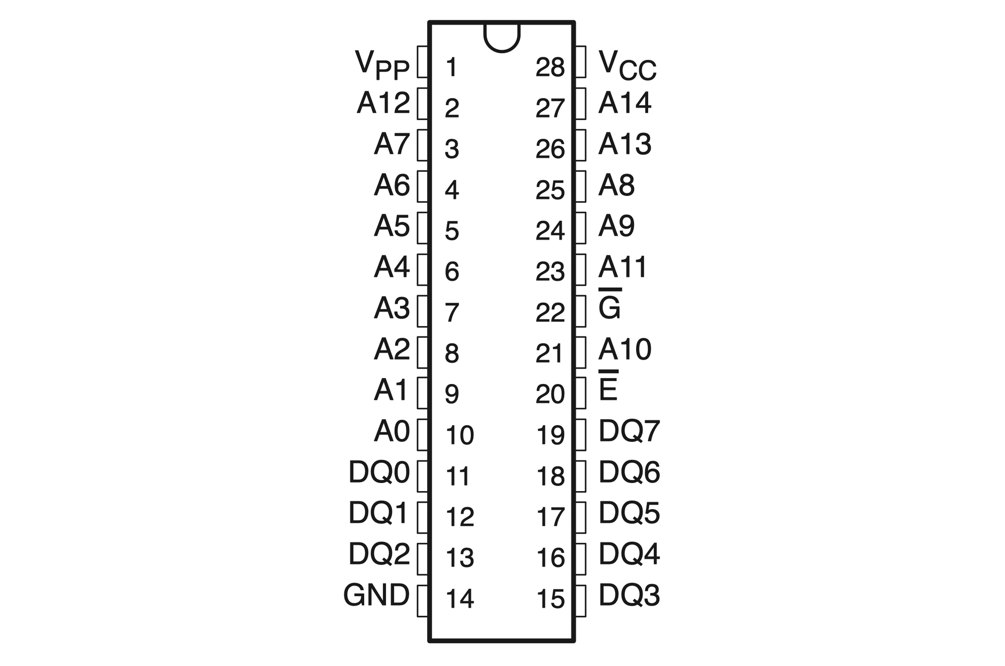
The Vpp pin is used to apply the higher programming voltage to the chip, and otherwise should be at Vcc supply potential. /E is the chip enable, and must be set low to read, write, or program the chip. In my case, I tied /E directly to the Z80's /MREQ (Memory REQuest) control signal. No decoding was needed since there was only the one EPROM connected to the address & data bus. /G is the output enable, which when set low, will put the contents of the memory location set at the address pins out onto the DQ0 - DQ7 pins. I connected /G to the Z80's /RD (ReaD) control signal.
With the EPROM connected to the address bus, data bus, /MREQ, & /RD signals, I started the computer and the result is visible in the YouTube video below:
After successfully connecting an EPROM to my breadboarded Z80, part 3 of this series will chronicle adding volatile memory, A.K.A. RAM!
If you haven't already subscribed to my blog, and would like to be notified by email whenever I post new content, please click on one of the subscribe links. It's free and your contact information will not be shared or sold to anyone.